Reinforcing bar binding machine

a technology of reinforcement bars and binding machines, applied in the field of reinforcement bars binding machines, can solve the problems of large amount of wire shavings accumulated and operation failure, and achieve the effect of easy and reliable removal

Active Publication Date: 2009-11-19
MAX CO LTD
View PDF3 Cites 13 Cited by
  • Summary
  • Abstract
  • Description
  • Claims
  • Application Information

AI Technical Summary

Benefits of technology

[0009]One or more embodiments of the invention provide a reinforcing bar binding machine in which wire shavings accumulated in a wire feeding device portion can be easily and reliably removed by air blow or a brush.

Problems solved by technology

Therefore, when the feed gears are used all day long, a large amount of wire shavings are accumulated.
As a result, when a large amount of wire shavings become attached, this may cause an operation failure.
Also, there is a possibility that the wire shavings enter a guide tube which guides the feeding of the wire and clog it.
However, when using air blow, wire shavings are pushed into the inside of the binding machine body by the pressure of the air.

Method used


Image

  • Reinforcing bar binding machine
  • Reinforcing bar binding machine
  • Reinforcing bar binding machine

Examples


Embodiment Construction

[0031]An exemplary embodiment of the invention is described in reference to drawings.

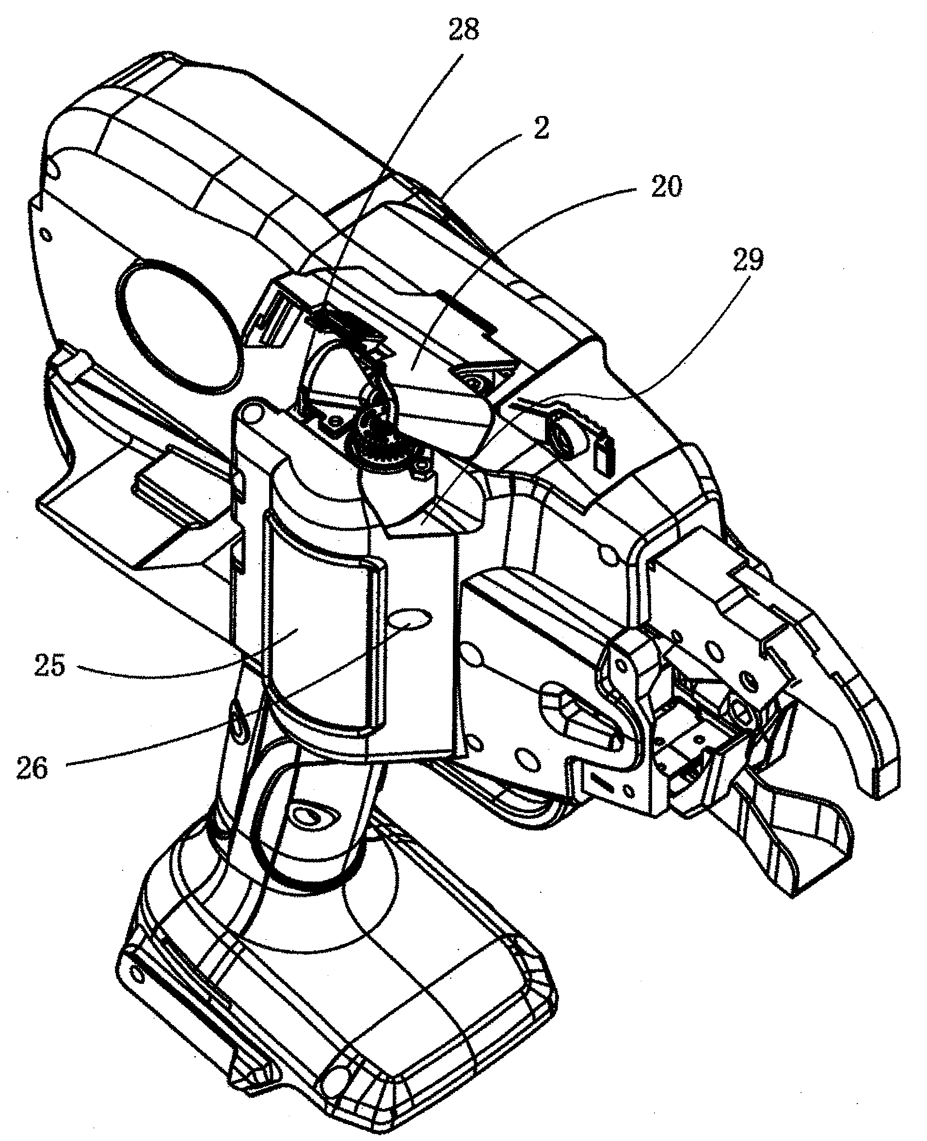
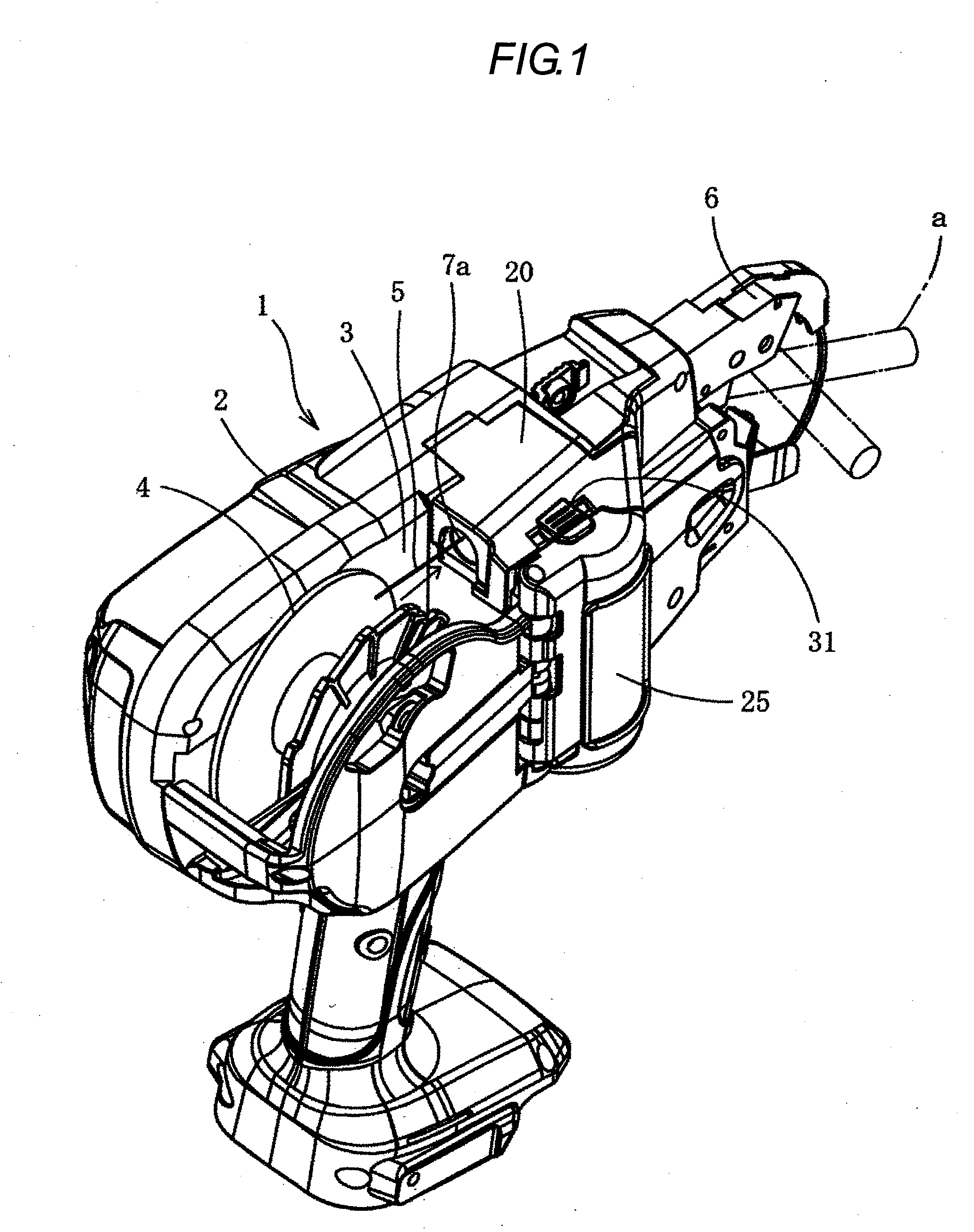
[0032]In FIG. 1 to FIG. 3, the reference numeral 1 denotes a reinforcing bar binding machine. In the reinforcing bar binding machine 1, in a housing chamber 3 provided in a binding machine body 2, a wire reel 4 around which a reinforcing bar binding wire 5 is wound is fitted, and a predetermined length of the wire 5 is fed to a guide part 6 provided on the tip end of the binding machine body 2 while rotating the wire reel 4, and the guide part 6 curls the wire 5 and feeds out the wire to the circumference of the reinforcing bars a disposed on the inner side of the guide part 6 and winds the wire around the reinforcing bars a, and then the root side of the wire 5 is cut, and the wound portion is twisted to bind the reinforcing bars a.

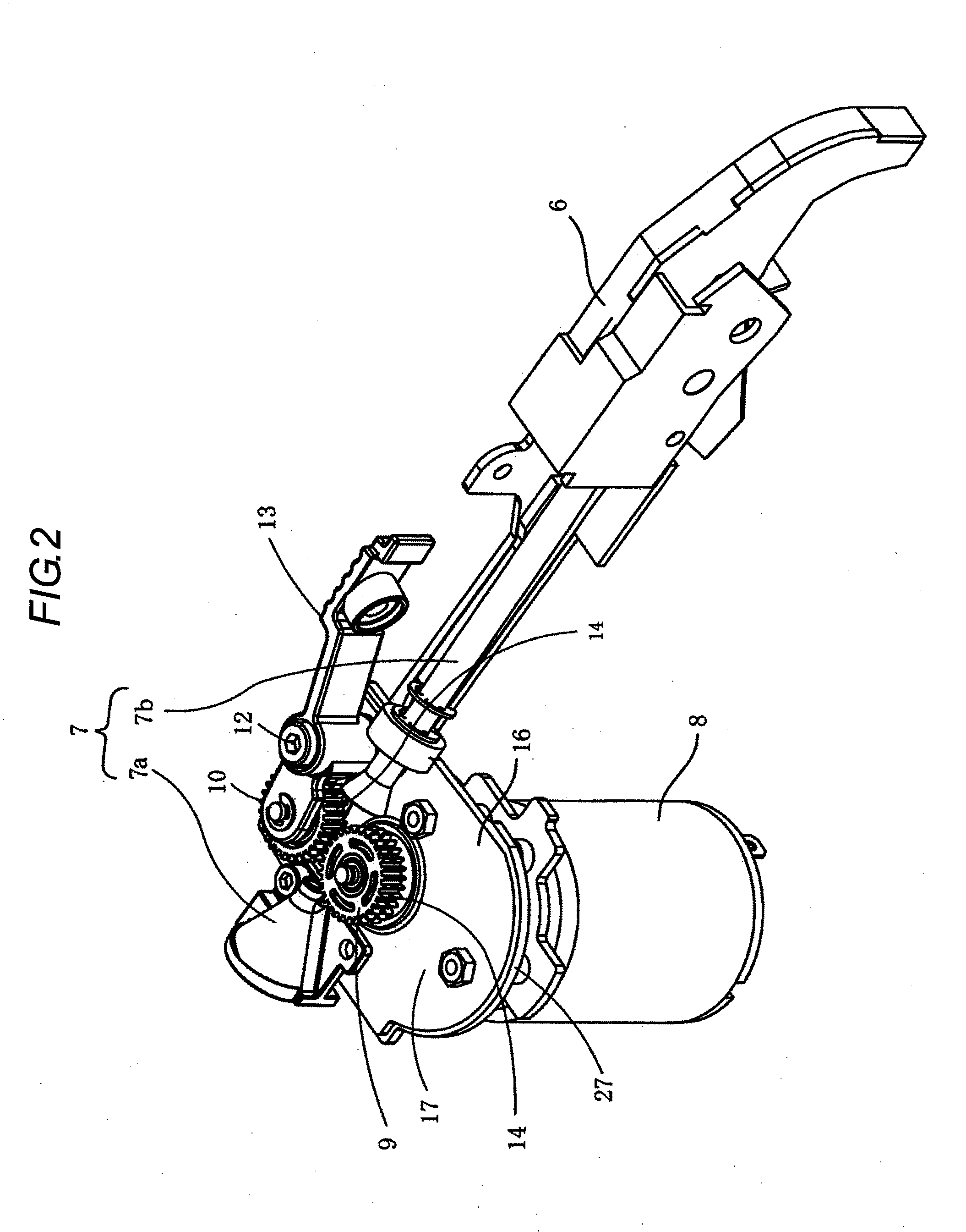
[0033]Between the housing chamber 3 and the guide part 6, a guide tube 7 through which the wire 5 is inserted is provided as shown in FIG. 2, and at the middle of the gu...


PUM

PropertyMeasurementUnit
circumferenceaaaaaaaaaa
contact frictionaaaaaaaaaa
corrosion proofingaaaaaaaaaa

Abstract

A reinforcing bar binding machine is provided with a pair of feed gears for feeding a wire from a wire reel mounted on a binding machine body; an electric motor for driving the feed gears; a partition plate provided between the feed gears and the electric motor to partition the feed gears and the electric motor; and first and second discharge portions for discharging wire shavings. The partition plate is surrounded by a wall except for portions of the partition plate being adjacent to the first and second discharge portions. The first and second discharge portions are disposed so that the partition plate positions between the first and second discharge portions.

Description

BACKGROUND OF THE INVENTION[0001]1. Field of the Invention[0002]The present invention relates to a reinforcing bar binding machine in which a wire is pulled out from a wire reel around which the reinforcing bar binding wire is wound in a housing chamber provided in a binding machine body, fed out to a circumference of reinforcing bars from a tip end of the binding machine body and wound around the reinforcing bars and then twisted to bind the reinforcing bars, wherein wire shavings accumulated around a wire feeding mechanism which pulls out the wire and feeds can be easily removed.[0003]2. Background Art[0004]In this type of reinforcing bar binding machine, a reinforcing bar binding wire is wound around a wire reel, and fed out to the tip end through a wire passage provided in the binding machine body. In the wire passage, a wire feeding device is provided. This feeding device includes a pair of feed gears disposed on both sides of the wire passage, and a wire is inserted between th...

Claims


Application Information

Patent Timeline
Patent Type & Authority Applications(United States)
IPC IPC(8): E04G21/12B21F23/00B21F15/04
CPCB25B25/00E04G21/123
Inventor NAGAOKA, TAKAHIRO
Owner MAX CO LTD
Why Eureka
Try Eureka