Surface treatments and coatings for atomization

a technology of surface treatment and atomization, which is applied in the direction of medical atomizers, liquid spraying devices, machines/engines, etc., can solve the problems of non-uniform liquid film, broken droplets, and current atomizers without means to ensure, so as to promote the atomization of liquid and reduce the mean drop size

Inactive Publication Date: 2009-11-19
GENERAL ELECTRIC CO
View PDF7 Cites 23 Cited by
  • Summary
  • Abstract
  • Description
  • Claims
  • Application Information

AI Technical Summary

Benefits of technology

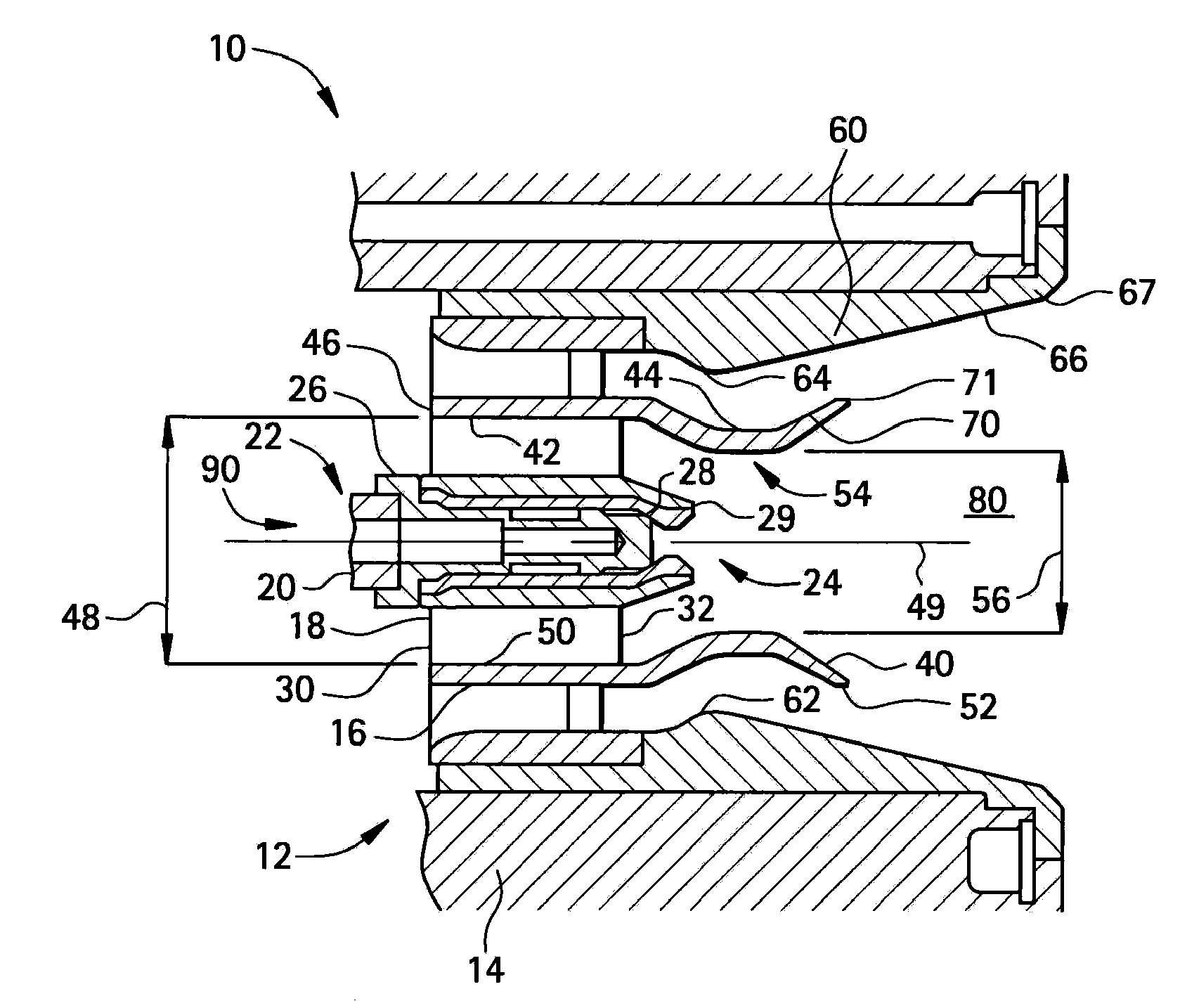
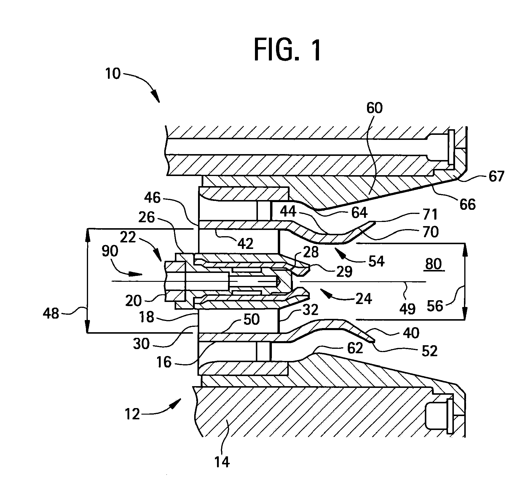
[0005]Disclosed herein are atomizers having a surface configured for promoting the atomization of a liquid. In one embodiment the atomizer includes a pre-filming region comprising a surface configured to reduce a mean drop size of an atomized liquid, wherein the surface has an effective contact angle, with reference to the atomized liquid, of less than about 30 degrees.
[0006]In another embodiment, an atomizer includes a pre-filming region;...

Problems solved by technology

The air streams can create hydrodynamic instabilities in the liquid film and cause it to break up into droplets.
Current atomizers have no means to ensure that the liquid is spread into the neces...

Method used


Image

  • Surface treatments and coatings for atomization
  • Surface treatments and coatings for atomization
  • Surface treatments and coatings for atomization

Examples


example 1

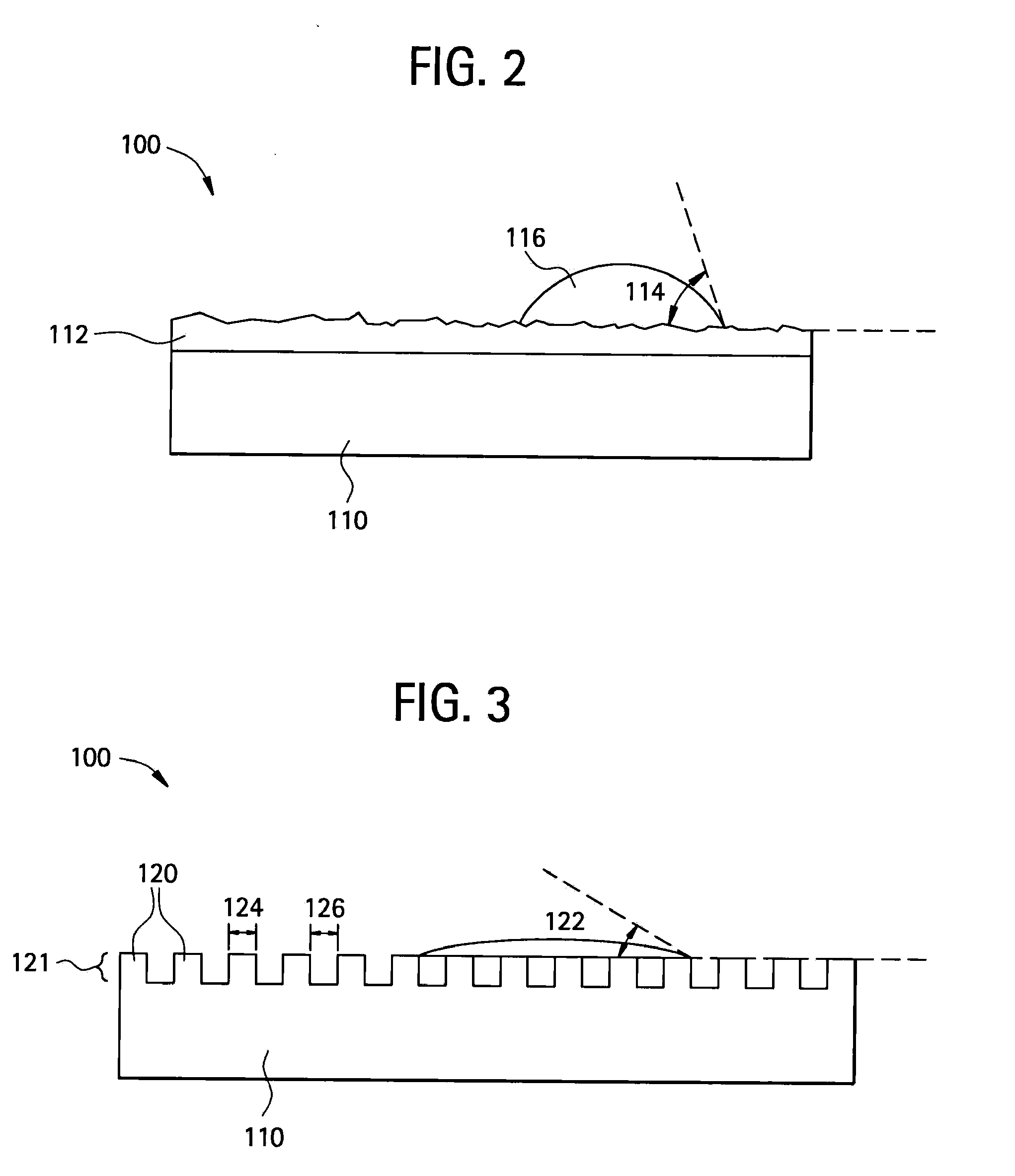
[0066]Silicon substrates were provided via lithography with right rectangular prism post features about 3 micrometers in width (a) and having a variety of post spacings (b / a ratios) and aspect ratios (h / a). The substrates were then placed in a chamber with a vial of liquid fluorsilane (FS), and the chamber was evacuated to allow the liquid to evaporate and condense from the gas phase onto the silicon substrate, thereby creating a hydrophilic film on the surface. The effective Wenzel state contact angle was recorded as a function of b / a ratio. FIG. 8 graphically illustrates the trend of varying the b / a ratio to reduce the effective contact angle. Three surfaces having nominal contact angles (CAn) of 50, 60, and 70 degrees respectively were textured with the rectangular post surface features. As shown in FIG. 8, the effective contact angle is lowered (as low as about zero degrees) as the relative spacing between each post is reduced. Moreover, increasing the aspect ration can result i...

example 2

[0069]FIG. 11 is a plot of effective contact angles (degrees) versus relative spacing of surface features (spacing dimension (b) divided by width dimension (a)). The graph shows a variety of hydrophilic / superhydrophillic surfaces that could be employed in the pre-filming and / or lip regions of an atomizer. The surface features were posts protruding from the surface and had a width dimension (a) of about 3 micrometers. As seen in the figure, the effective contact angle of the surface increased from about 25 degrees to about 40 degrees when the relative spacing of the post features was increased from about 4 to about 10. When the relative spacing of the features were closer (e.g. a b / a to of less than about 4), the effective contact angle of the surface was about 0 degrees or completely wetting.

[0070]Ranges disclosed herein are inclusive and combinable (e.g., ranges of “up to about 25 wt %, or, more specifically, about 5 wt % to about 20 wt %”, is inclusive of the endpoints and all int...


PUM


Abstract

An atomizer, comprising a pre-filming region comprising a surface configured to reduce a mean drop size of a liquid to be atomized, wherein the surface has an effective contact angle, with reference to the liquid, of less than about 30 degrees; and a lip portion disposed at an end of the pre-filming region and configured to create hydrodynamic instabilities in a liquid film, wherein the lip portion comprises an alternating pattern of wetting and non-wetting surfaces, wherein the non-wetting surface comprises a contact angle, with reference to the liquid, of greater than 90 degrees, and the wetting surface comprises a contact angle, with reference to the liquid, of less than 90 degrees.

Description

BACKGROUND OF THE INVENTION[0001]The present disclosure relates to articles having surfaces engineered to promote selective wetting of the surfaces by liquids. More particularly, this invention relates to enhancing atomization by increasing the wettability of pre-filming region surfaces and inducing hydrodynamic instabilities in selective regions of the atomizer.[0002]Atomization generally refers to the conversion of bulk liquid into a spray or mist (i.e. collection of drops), often by passing the liquid through a nozzle. An atomizer is an apparatus for achieving atomization. Common examples of atomization systems can include: gas turbines, carburetors, airbrushes, misters, spray bottles, and the like. In internal combustion engines for example, fine-grained fuel atomization can be instrumental to efficient combustion.[0003]Current air-blast atomizers spread liquid from a nozzle orifice into a film on one or more pre-filming regions. The atomizers can use pressure, airflow, electros...

Claims


Application Information

Patent Timeline
IPC IPC(8): A61M11/02
CPCB05B7/068B05B7/066F02K1/38
Inventor VARANASI, KRIPA KIRANBHATE, NITINGOLDMEER, JEFFREY SCOTTMYERS, GEOFFREY DAVID
Owner GENERAL ELECTRIC CO
Why Eureka
Try Eureka