Light Scanning Photoelectric Switch

a photoelectric switch and light scanning technology, applied in the direction of discharge tube/lamp details, instruments, using reradiation, etc., can solve the problems of air tightness defect, easy air tightness defect, and uneven tightening of fixing members, so as to prevent a reduction in the strength of the cover, prevent uneven tightening of the fixing member, and improve the bending rigidity of the cover

Inactive Publication Date: 2009-11-19
KEYENCE
View PDF25 Cites 31 Cited by
  • Summary
  • Abstract
  • Description
  • Claims
  • Application Information

AI Technical Summary

Benefits of technology

[0025]According to this aspect of the present invention, the both side portions of the cover are pressed against the sealing member in the state in which the cover is not fixed by the fixing member. Accordingly, it is possible to further prevent the uneven tightening of the fixing member when fixing the cover by the fixing member, and the cover can be correctly fixed with the fixing member even by an inexperienced person.
[0026]In the present invention, it is preferabl...

Problems solved by technology

In a case of this switch, since the front cover 101 is in U-shape, tightening of screws can be uneven depending on an attachment order of fixing screws to the front cover 101, resulting in a defect in airtightness.
In this case, a defect in a...

Method used


Image

  • Light Scanning Photoelectric Switch
  • Light Scanning Photoelectric Switch
  • Light Scanning Photoelectric Switch

Examples


first embodiment

[0044]Hereinafter, one embodiment of the present invention will be described with reference to the drawings.

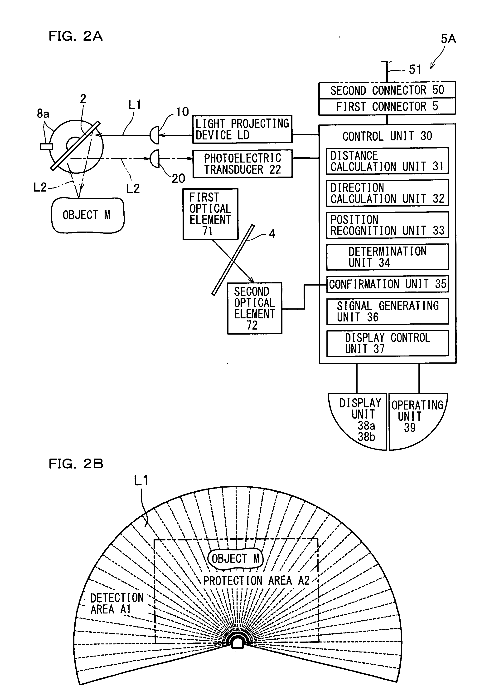
[0045]A light scanning photoelectric switch according to the present embodiment, for example, is connected to an external device such as a robot, and outputs a safety signal indicating that operation of the connected external device is either enabled or disabled. For example, when an object M such as a human body is detected within a protection area A2 that has been previously set as shown in FIG. 2B, the photoelectric switch of the present embodiment, in a predetermined mode, outputs an operation disable signal to prohibit (disable) the operation of the external device connected to the photoelectric switch. The protection area A2 is previously set within a detection area A1 and recorded.

Optical Path

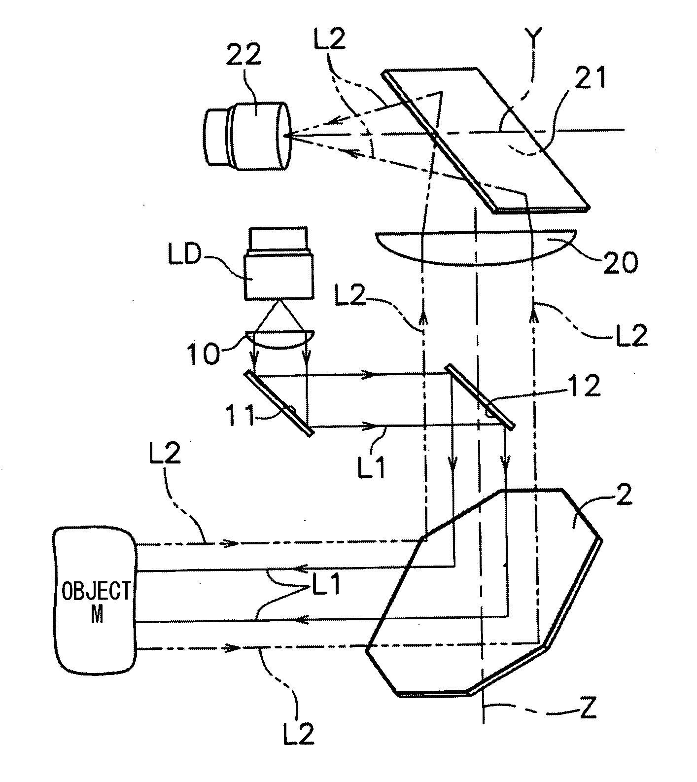
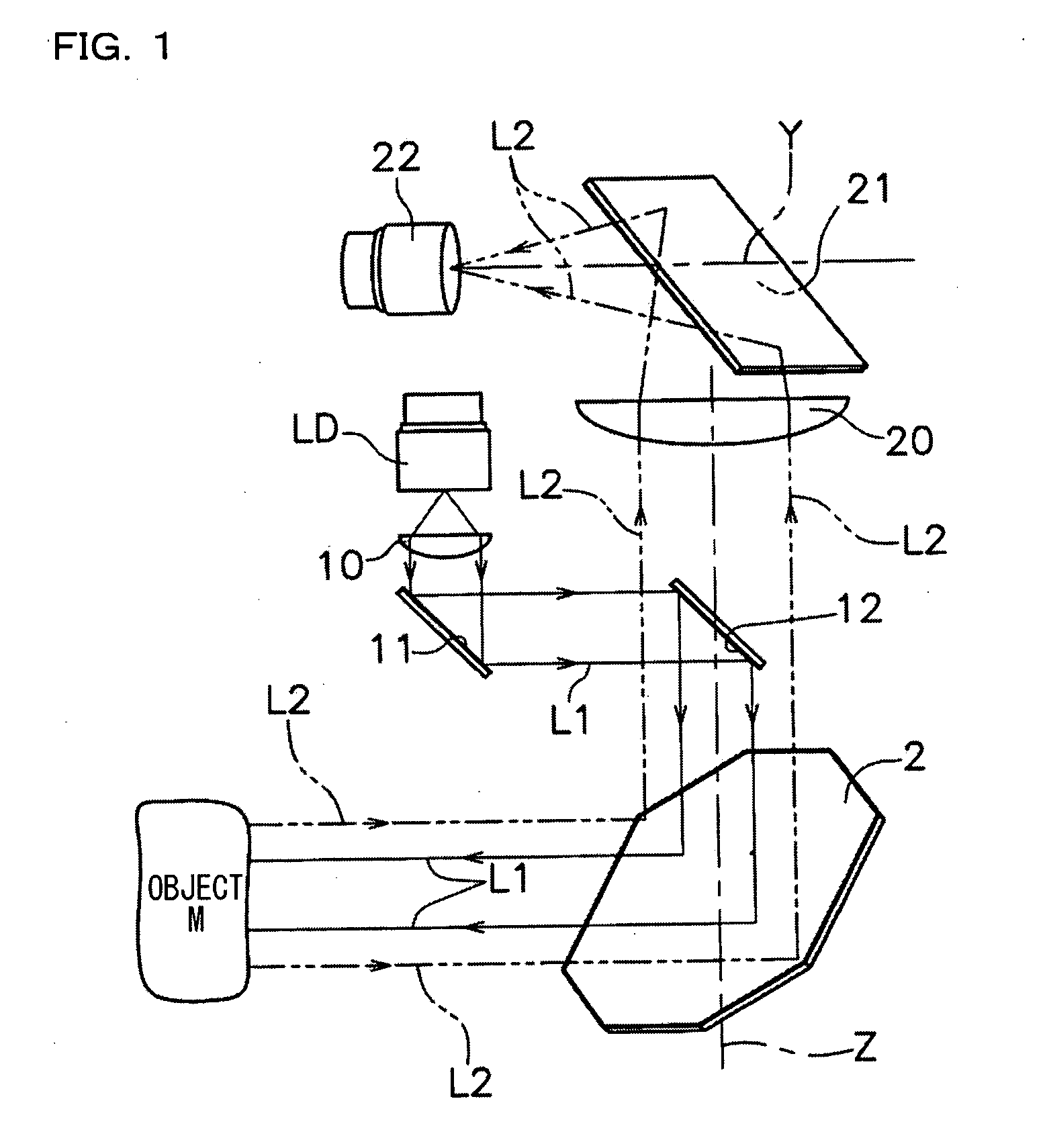
[0046]The photoelectric switch of the present embodiment detects the object M by, for example, scanning light such as a laser beam. An optical system is first described.

[0047]Light...


PUM


Abstract

Provided is a light scanning photoelectric switch that can be attached to a cover correctly even by an inexperienced person. The light scanning photoelectric switch includes: a casing that contains a light scanning unit and a photoelectric transducer and has an opening substantially in U-shape in cross section perpendicular to an axis; a cover that is detachably provided for the casing and is for covering the opening of the casing; an elastically deformable sealing member provided between the casing and the cover; an engagement unit provided for the cover and the casing so that the cover engages with the casing in a state in which the sealing member is compressed in an attachment direction along which the cover is attached to the casing; and a fixation portion capable of receiving a fixing member that compresses the sealing member in a direction different from the attachment direction in a state in which the cover engages with the casing.

Description

CROSS-REFERENCE TO RELATED APPLICATIONS[0001]The present application claims foreign priority based on Japanese Patent Application No. 2008-126625, filed May 14, 2008, the contents of which is incorporated herein by reference.BACKGROUND OF THE INVENTION[0002]1. Field of the Invention[0003]The present invention relates to a light scanning photoelectric switch.[0004]2. Description of the Related Art[0005]Conventionally, there has been proposed a scanning device that detects, using light such as laser, whether or not an object is present within a predetermined area that has been previously set (see Japanese Unexamined Patent Publication No. 4-310890 (Abstract), Japanese Unexamined Patent Publication No. 3-175390 (FIG. 1), and U.S. Pat. No. 5,455,669 (FIG. 4)).[0006]A light scanning photoelectric switch is a so-called safety scanner or safety laser scanner, and scans over a detection area with light such as laser, receives the scanning light that has been reflected within the detection a...

Claims


Application Information

Patent Timeline
IPC IPC(8): H01J40/14
CPCG01S7/4813G01S17/42G01S17/08G01S17/026G01S17/04
Inventor TAGASHIRA, TSUYOSHI
Owner KEYENCE
Why Eureka
Try Eureka