Coil unit and electronic apparatus using the same

a technology of electronic equipment and coil unit, which is applied in the direction of transformer/inductance details, printed inductances, inductances, etc., can solve the problems of difficult to maintain the shape of the coil unit, and reduce the flexibility of the use. , to achieve the effect of greater flexibility in the insertion position and greater flexibility in the insertion method

Active Publication Date: 2009-11-19
138 EAST LCD ADVANCEMENTS LTD
View PDF11 Cites 71 Cited by
  • Summary
  • Abstract
  • Description
  • Claims
  • Application Information

AI Technical Summary

Benefits of technology

[0021]An electronic apparatus according to another aspect of the invention includes an insertion part into which the above-mentioned coil unit is to be inserted and a main body terminal to be connected to the external connection terminal of the coil unit. Since the coil unit is downsized or slimmed down, it has greater flexibility in its insertion position in the insertion part of the electronic apparatus and in its insertion space. Also, the coil unit has greater flexibility in its insertion method such as slot-in or insertion into a lid such as a battery lid.

Problems solved by technology

Also, the battery pack lid (2) is available only as a battery pack; therefore, its use condition, that is, its flexibility in usage is significantly restricted.
Depending on the materials of the coil and magnetic substance, it is difficult to maintain the shape of the coil unit with only the coil and magnetic substance; however, integration with the wiring substrate, which is a rigid body, allows the coil unit to maintain its shape.
This slims down the coil unit.
If a foreign object intrudes into the air-core having a high magnetic flux density of the air-core coil, heating caused by an eddy current generated by the foreign object becomes extremely significant.

Method used


Image

  • Coil unit and electronic apparatus using the same
  • Coil unit and electronic apparatus using the same
  • Coil unit and electronic apparatus using the same

Examples


Embodiment Construction

[0038]Now, a preferred embodiment of the invention will be described in detail. The embodiment described below does not unduly limit the invention as set forth in the appended claims. Also, not all the configurations described in the embodiment are essential as means for solving the above-mentioned problems.

[0039]1. Charging System

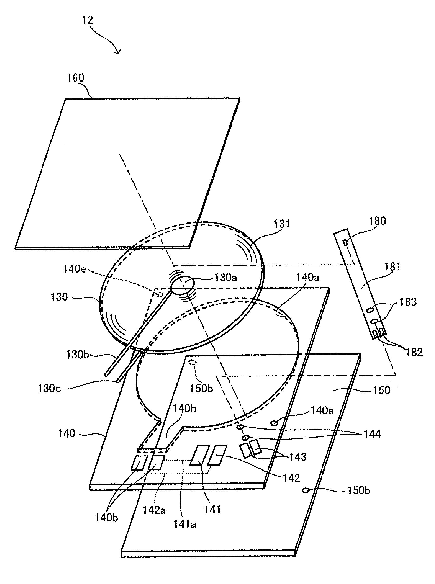
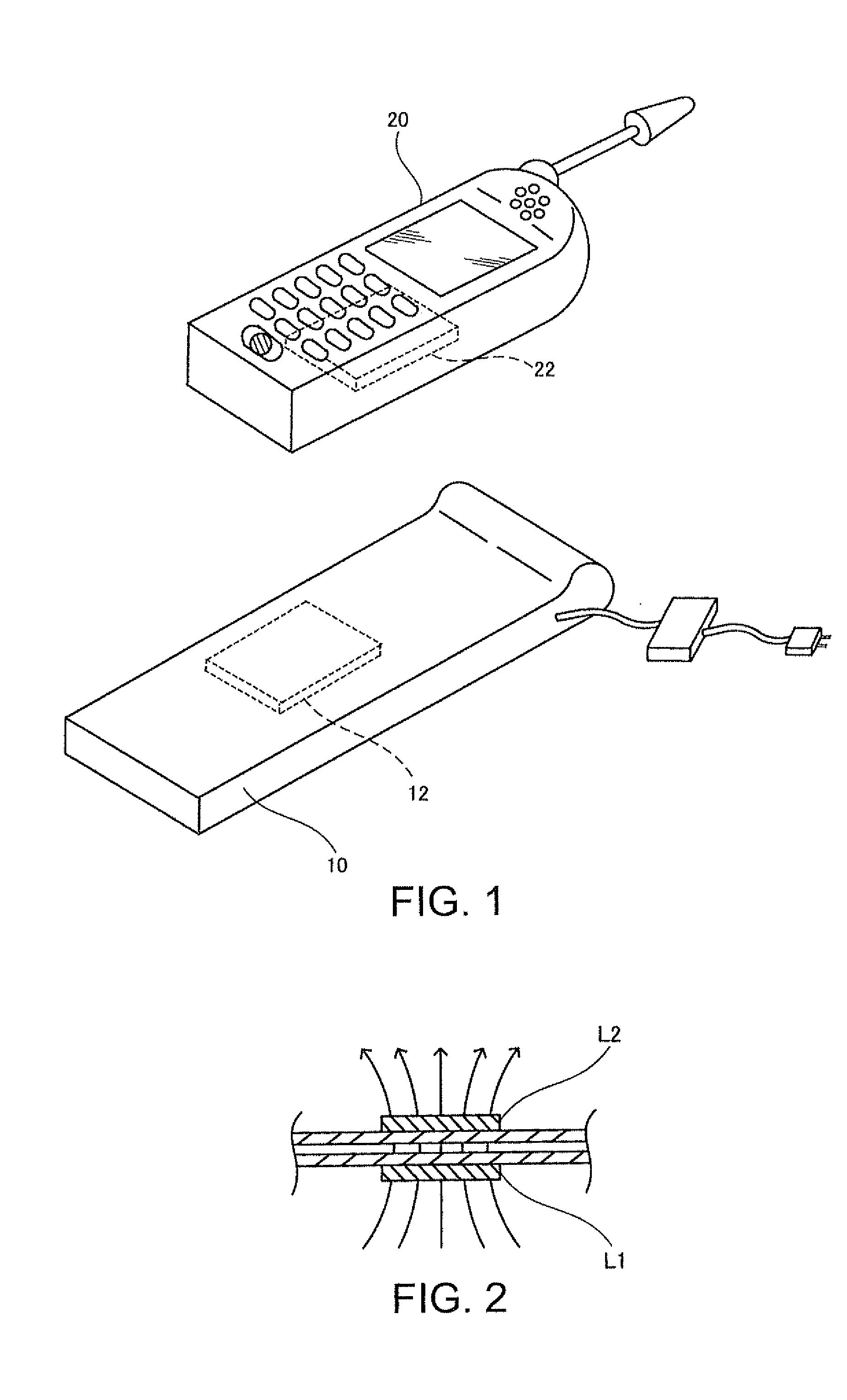
[0040]FIG. 1 is a drawing schematically showing a charger 10, which is also an example of an electronic apparatus, and a cell phone 20, which is an example of an electronic apparatus changed by the charger 10. FIG. 1 shows the cell phone 20 to be transversely placed on the charger 10. The cell phone 20 is charged by the charger 10 by means of contactless power transmission using an electromagnetic induction action generated between a coil of a coil unit 12 of the charger 10 and a coil of a coil unit 22 of the cell phone 20.

[0041]The charger 10 and cell phone 20 may each have a positioning structure. For example, the charger 10 may have a positioning protru...


PUM

PropertyMeasurementUnit
frequencyaaaaaaaaaa
temperatureaaaaaaaaaa
resistanceaaaaaaaaaa

Abstract

A coil unit includes a coil formed by winding a coil wire, a wiring substrate, and a magnetic substance for receiving magnetic lines of force generated by the coil. The wiring substrate includes a connection terminal connected to both ends of the coil, an external connection terminal, and a wiring pattern for connecting the connection terminal and the external connection terminal. No circuit element other than the coil is mounted on the wiring substrate.

Description

BACKGROUND[0001]1. Technical Field[0002]Several aspects of the present invention relates to a coil unit suitable for contactless power transmission and an electronic apparatus or the like using the coil unit.[0003]2. Related Art[0004]There is known contactless power transmission that uses electromagnetic induction to transmit power without using a metal contact. As applications of contactless power transmission, charging of a cell phone, charging of a home appliance (e.g., a handset), and the like have been proposed.[0005]In recent years, cell phones are required to be downsized further. For this reason, a coil unit for transmitting power must also be further downsized, particularly, in the thickness dimension. For the purpose of providing a battery pack interface whose use allows charging a cell phone including a battery pack by only placing the cell phone on a power transmission apparatus, JP-A-2006-311712 discloses a technology for transmitting power to a cell phone (1) including...

Claims


Application Information

Patent Timeline
Patent Type & Authority Applications(United States)
IPC IPC(8): H01F27/28H01F27/29H01F38/14
CPCH01F17/0006H04B1/3883H01F2038/143H01F38/14
Inventor OKADA, HIROFUMIKONDO, YOICHIRO
Owner 138 EAST LCD ADVANCEMENTS LTD
Why Eureka
Try Eureka