Vehicle temperature warning system

a technology for vehicle temperature and warning system, which is applied in the direction of braking discs, instruments, roads, etc., can solve the problems of damage to or failure of degradation of the lubricant and/or the seal, damage to the wheel end assembly and/or the axle spindle end,

Active Publication Date: 2009-11-19
HENDRICKSON USA L L C
View PDF9 Cites 34 Cited by
  • Summary
  • Abstract
  • Description
  • Claims
  • Application Information

AI Technical Summary

Benefits of technology

[0014]The objectives of the present invention include providing a vehicle temperature warning system which eliminates relatively fragile thermal sensors that are potentially susceptible to damage and / or premature wear.
[0015]Another objective of the present invention is to provide a vehicle temperature warning system that improves detection of excessive heat in the axle spindle end and / or the wheel end assembly due to placement of the detection means adjacent the bearing assemblies.
[0016]A further objective of the present invention is to provide a vehicle temperature warning system that avoids contamination and pressure build-up in the wheel end assembly.
[0017]Yet another objective of the present invention is to provide a vehicle temperature warning system that is easily accessible for both replacement and / or maintenance of the system.
[0018]Still a further objective of the present invention is to provide a vehicle temperature warning system that is simple, reliable and cost efficient as compared to prior art vehicle temperature warning systems.

Problems solved by technology

Repeated excessive speed or excessive braking of the vehicle often generates a large amount of heat in components of the wheel end assembly and / or the axle spindle end, in turn heating the bearing assembly lubricant and / or the bearing assembly seal, which may cause degradation of the lubricant and / or the seal.
If the lubricant degrades, rotation of the wheel hub about the axle spindle end may become impaired and can result in damage to or failure of the wheel end assembly and / or the axle spindle end.
Alternatively, if the seal degrades, the lubricant may escape, or external contaminants may pass into the bearing assemblies, which can impair the rotation of the wheel hub about the axle spindle end and may potentially damage the wheel end assembly and / or the axle spindle end.
It is this impaired rotation of the wheel end assembly about the axle spindle end that produces excessive heat in the wheel end assembly and in the axle spindle end.
Similar potential damage may be caused by installation problems which can detrimentally affect the lubricant and / or bearing assemblies, and thus allow excessive heat to be generated in the wheel end assembly components and / or the axle spindle end.
Such installation problems include situations in which the lubricant accidentally may have been omitted from the bearing assemblies, and / or over-tightening of the bearing assembly retaining nuts, which can overload the bearing assemblies.
Moreover, absent the problem conditions set forth above, it is well documented and known to those having ordinary skill in the art that the bearing assemblies themselves typically exhibit excessive heat prior to failure.
Such sealed bearing assemblies are known in the art as being non-serviceable, and thus typically cannot readily be opened in order to replace or add lubricant if the lubricant escapes the assembly or degrades.
Rather, sealed bearing assemblies are typically removed from service and replaced if such a problem does occur.
Because multiple trailers, each possibly having multiple axles and multiple wheel end assemblies, may be pulled by a single tractor, the chance that a given wheel end assembly and / or axle spindle end may become impaired from the above-described conditions without detection by the vehicle operator increases.
Such conditions may indicate degradation of or a lack of the proper amount of lubricant in the bearing assemblies, degradation of the bearing assembly seals, contamination in the bearing assemblies, an overloading of the bearing assemblies, or the breakdown of the bearing assembly itself.
These systems typically require complex wiring systems that make them costly to manufacture and difficult to install on the vehicle.
Moreover, these systems also include thermal sensors which are relatively fragile and which are located within the axle spindle end of the axle which makes them difficult to replace when they become damaged or simply wear out due to normal wear and tear on the system.
However, these systems also have demonstrated potential problems in that interference between the transmitter and the receiver can cause false indications of a problem condition when no problem condition actually exists.
However, those systems have located the fusible material within the axle spindle end which, when activated by exposure to an excessive heat condition, can release contaminants, i.e., the melted fusible material, into the wheel end assembly, and / or cause pressure to build in the wheel end assembly which can potentially cause the bearing assembly seal to leak, which in turn can potentially cause premature failure of the bearing assemblies.

Method used


Image

  • Vehicle temperature warning system
  • Vehicle temperature warning system
  • Vehicle temperature warning system

Examples


Embodiment Construction

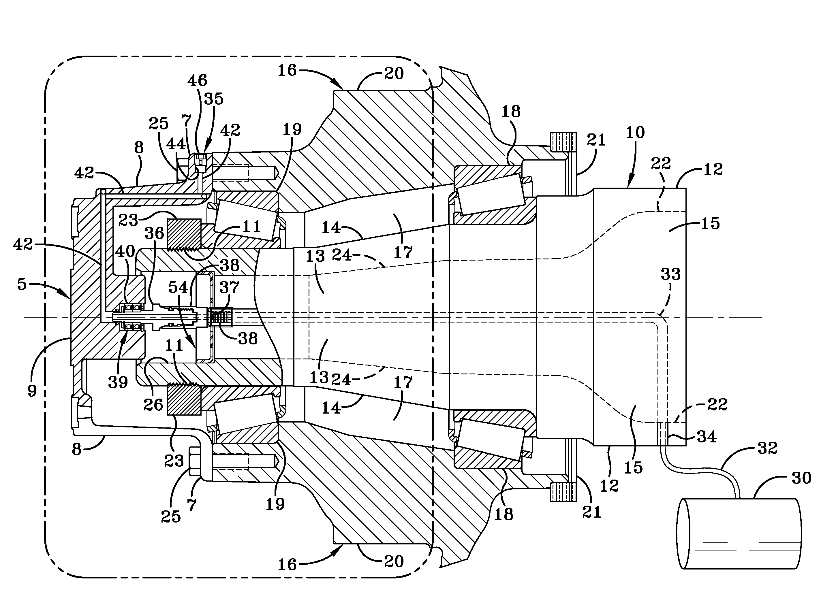
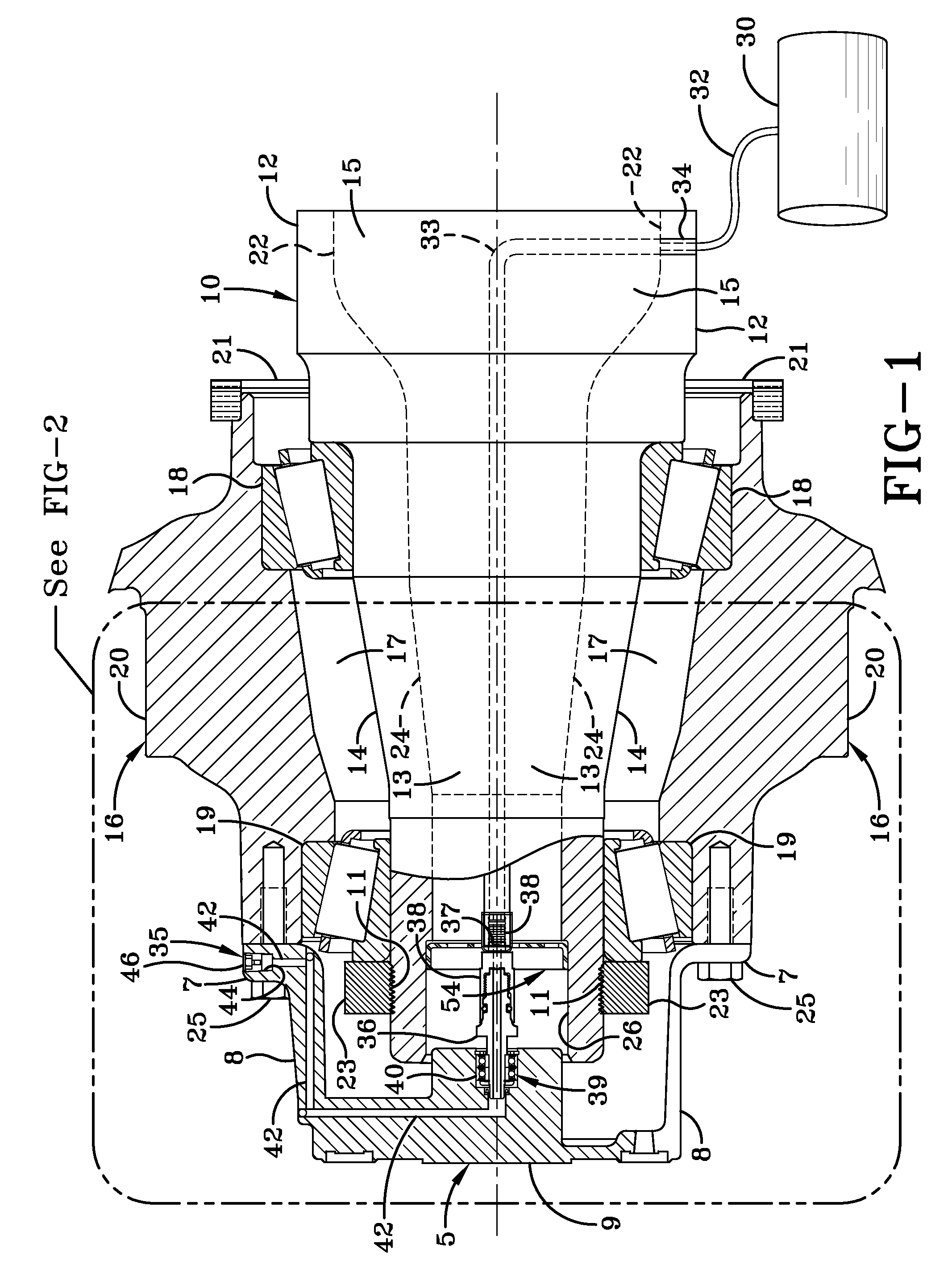
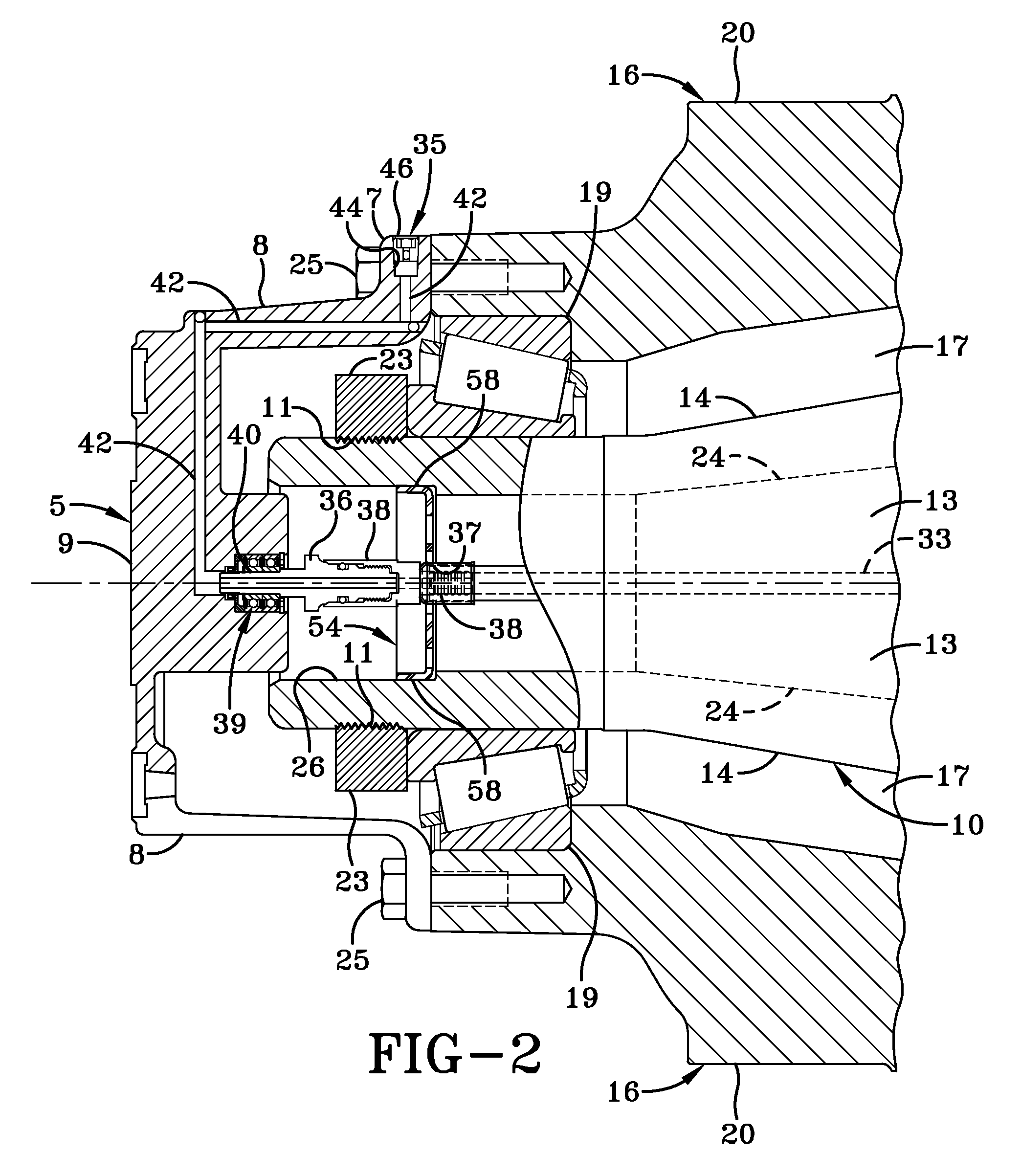
[0033]Turning now to FIG. 1, a preferred embodiment vehicle temperature warning system 35 of the present invention is shown in conjunction with a portion of a typical axle 10 and a wheel end assembly 16. In order to better understand the environment in which vehicle temperature warning system 35 of the present invention is utilized, axle 10 and wheel end assembly 16 each now will be described.

[0034]Axle 10 includes an axle central tube 12 and a pair of axle spindle ends 14 (only one shown), each one of which is located on a respective one of a pair of outboard ends of the central tube. Wheel end assembly 16 includes inboard and outboard bearing assemblies 18 and 19, respectively, which are mounted on axle spindle end 14, and a wheel hub 20 that is mounted on the bearing assemblies in a well-known manner, thereby enabling the wheel hub to rotate about the axle spindle end. For the sake of clarity, only one axle spindle end 14 and wheel end assembly 16 will be described herein, though...


PUM


Abstract

A temperature warning system for a vehicle includes a thermal plug disposed on the wheel end assembly of the vehicle. The thermal plug is in fluid communication with an air supply and with a flow sensor. The flow sensor is operatively connected to a warning light or indicator. Excessive heat in the axle spindle end and / or the wheel end assembly causes a fusible material in the thermal plug to melt allowing air to flow from the air supply through the thermal plug thus activating the flow sensor. The flow sensor in turn activates the warning light or indicator alerting the driver of the vehicle of a problem condition at the wheel end assembly and / or axle spindle.

Description

CROSS-REFERENCE TO RELATED APPLICATION[0001]This application claims the benefit of U.S. Provisional Application No. 61 / 053,873, filed on May 16, 2008.BACKGROUND OF THE INVENTION[0002]1. Field of the Invention[0003]The invention relates generally to the art of temperature warning systems for vehicles, and in particular to temperature warning systems for the non-drive axles of heavy-duty vehicles, such as tractor-trailers or semi-trailers, and straight trucks, which are capable of functioning during vehicle operation. More particularly, the invention relates to a vehicle temperature warning system which utilizes a thermal plug that includes a fusible material and which is located in or adjacent to the wheel end assembly of a heavy-duty vehicle. The thermal plug operates in conjunction with a pressurized air supply and a flow sensor to alert the driver of the vehicle of an undesirable temperature condition in the wheel end assembly and / or the axle spindle end during operation of the ve...

Claims


Application Information

Patent Timeline
Patent Type & Authority Applications(United States)
IPC IPC(8): B60Q1/00
CPCB60C23/003B60T5/00B60T17/221G01K13/08F16D65/12F16D2066/001B61K9/04B60C23/00318B60C23/00336B60C23/00345B60C23/00363
Inventor WILSON, MATT J.VANMETER, MATTHEWPADULA, SANTOCERVANTEZ, JESSE W.
Owner HENDRICKSON USA L L C
Why Eureka
Try Eureka