Wireless mesh network transit link topology optimization method and system

a topology optimization and wireless mesh technology, applied in the field of wireless mesh network transit link topology optimization method and system, can solve the problems of data transmission at a slower rate than could otherwise be achieved, network bottlenecks, and increased latency, and achieve the effect of quick and efficien

Inactive Publication Date: 2009-11-19
APPLE INC
View PDF1 Cites 91 Cited by
  • Summary
  • Abstract
  • Description
  • Claims
  • Application Information

AI Technical Summary

Problems solved by technology

While this redundancy creates a very reliable infrastructure for ensuring that data eventually passes through the network, the cost is that the shortest path is not always chosen and if a link has an impaired transmission rate with respect to other links in the path, the data is transmitted at a slower rate than could otherwise be achieved.
A transmitting node does not have the ability to see further down the path than the next hop, so the data is not always routed according to the most optimal overall route.
Automatic implementations of backhaul routing on the Wi-Fi access points may not prevent nodes from taking unnecessary hops through the mesh network, resulting in nodes having to perform several, e.g., 4-7, hops before reaching a wired network connection.
Additionally, some nodes physically located in the middle of mesh network may receive considerably more traffic than nodes located further toward the edge of the network, and the data flow stalls waiting for the node to become available.
Thus, a bottleneck is created in the network when there could potentially be other nodes available to route the data traffic and relieve congestion.
As a result, latency is increased and re-transmission of the data decreases throughput and capacity in a Wi-Fi mesh network.
Depending on the size of the wireless mesh network, this process can take several hours and does not necessarily yield the optimal routing configuration.
For larger networks, an engineer can easily miss generating the most optimal solution.

Method used


Image

  • Wireless mesh network transit link topology optimization method and system
  • Wireless mesh network transit link topology optimization method and system
  • Wireless mesh network transit link topology optimization method and system

Examples


Embodiment Construction

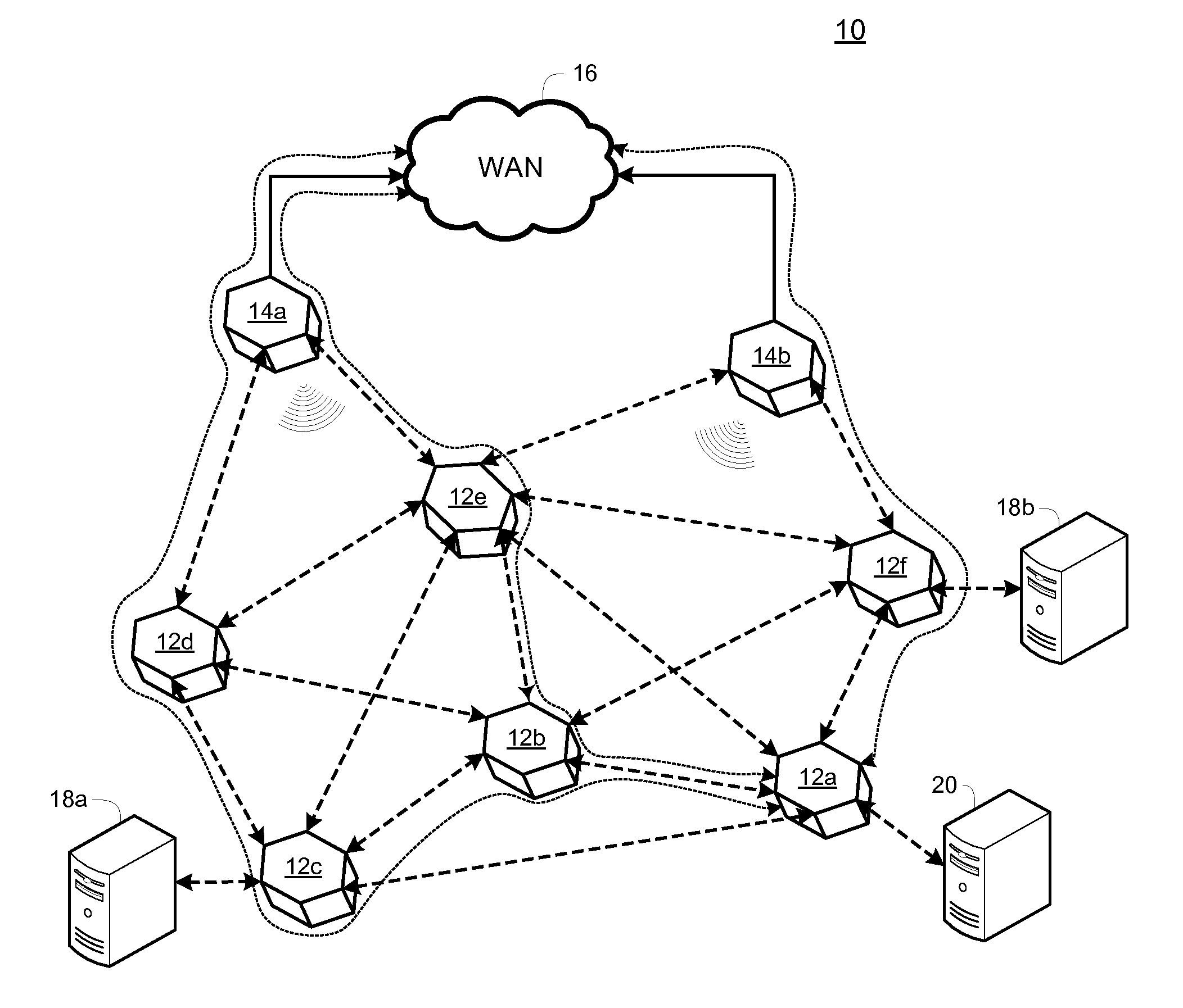
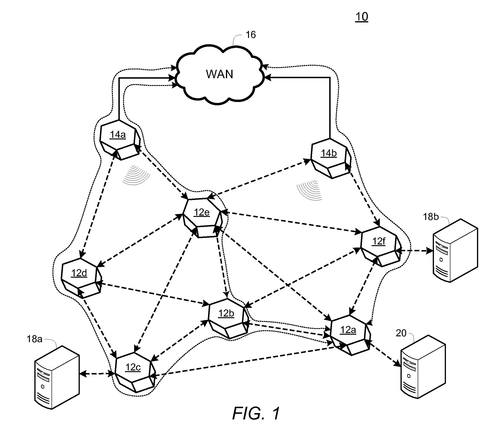
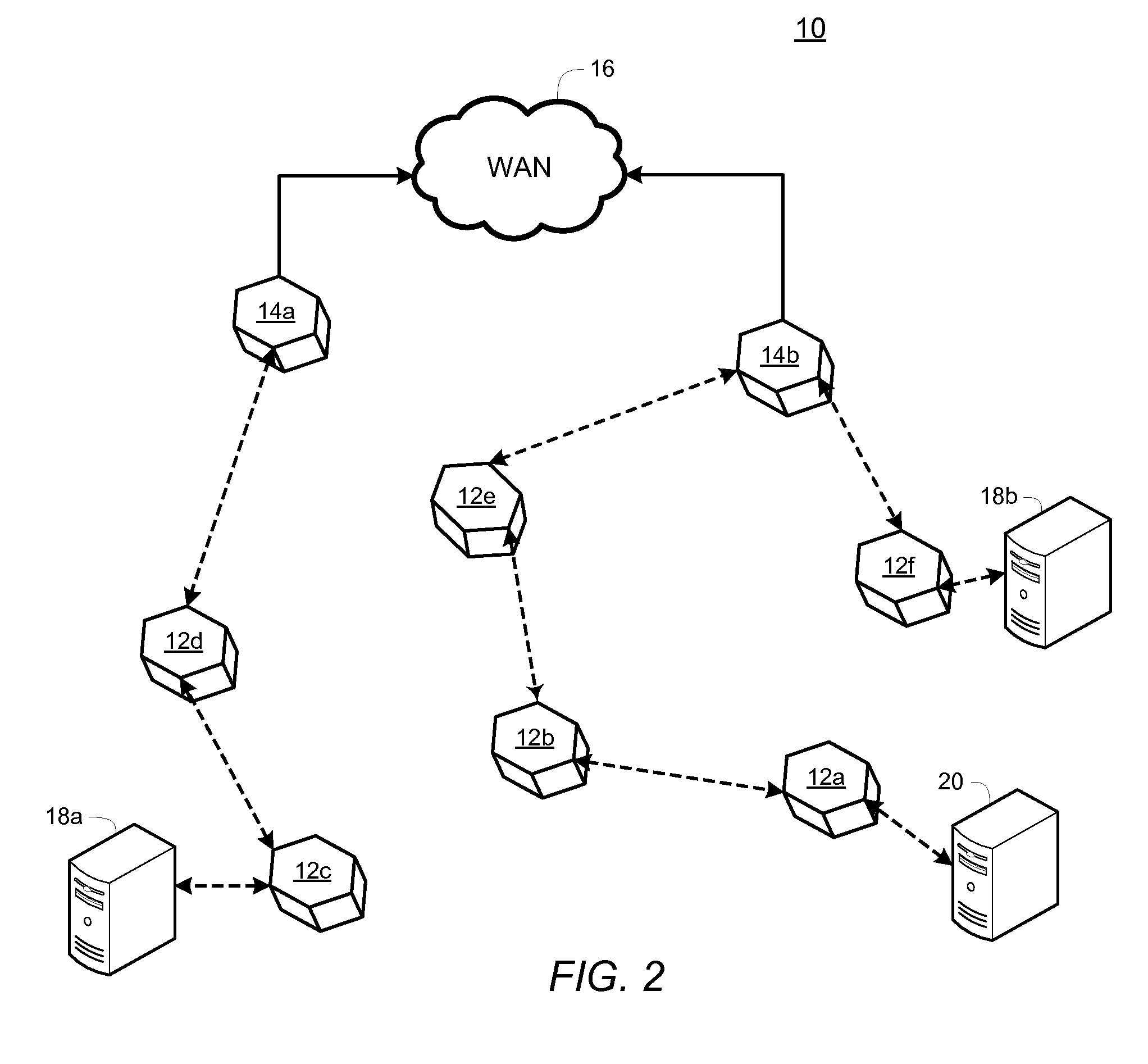
[0021]Before describing in detail exemplary embodiments that are in accordance with the present invention, it is noted that the embodiments reside primarily in combinations of apparatus components and processing steps related to implementing a system and method for generating an optimized backhaul routing topology in a wireless mesh network which allows data from each node to reach a network access point in a limited number of hops. Accordingly, the apparatus and method components have been represented where appropriate by conventional symbols in the drawings, showing only those specific details that are pertinent to understanding the embodiments of the present invention so as not to obscure the disclosure with details that will be readily apparent to those of ordinary skill in the art having the benefit of the description herein.

[0022]As used herein, relational terms, such as “first” and “second,”“top” and “bottom,” and the like, may be used solely to distinguish one entity or elem...


PUM


Abstract

A method and configuration manager generates a routing topology for a wireless mesh network. The wireless mesh network has a plurality of internal nodes, at least one edge node, and at least one originating device. A plurality of potential routing solutions is determined which contain a plurality of paths through the wireless mesh network from the at least one originating device to the at least one edge node such that data communicated from the at least one originating device reaches the at least one edge node in no more than a predetermined number of hops. Each potential routing solution is based on at least one measured wireless communication parameter between internal nodes. Metric calculations for each potential routing solution are computed to determine a preferred routing solution. The wireless mesh network is configured to route traffic using the preferred routing solution.

Description

CROSS-REFERENCE TO RELATED APPLICATION[0001]n / aSTATEMENT REGARDING FEDERALLY SPONSORED RESEARCH OR DEVELOPMENT[0002]n / aFIELD OF THE INVENTION[0003]The present invention relates generally to a method and system for optimizing routing paths in a communication network, and more specifically to a method and system for automatically generating an optimized backhaul routing topology in a wireless mesh network which allows data from each node to reach a network access point in an efficient number of hops.BACKGROUND OF THE INVENTION[0004]Mesh networking is one method used for routing data, voice and instructions between wireless access points (“AP”) called nodes. A node is a connection point, either a redistribution point or an end point, for data transmission. The nodes typically communicate using a predetermined protocol such as the protocol defined by the Institute of Electrical and Electronics Engineers (“IEEE”) standard 802.11, commonly called Wi-Fi. In general, a node has the ability ...

Claims


Application Information

Patent Timeline
Patent Type & Authority Applications(United States)
IPC IPC(8): H04L12/56H04L45/122
CPCH04L45/122H04W40/16H04W84/22H04W40/246H04W40/248H04W40/24
Inventor AGUIRRE, MARIANOMACINTOSH, DOUGLAS W. M.
Owner APPLE INC
Why Eureka
Try Eureka