Cutting Tool and Cutting Insert Therefor

a cutting tool and cutting insert technology, applied in the field of cutting tools, can solve the problems of reducing the jaw's ability to retain the cutting insert, increasing the maintenance cost of the tool, and affecting the cutting effect of the tool

Active Publication Date: 2009-11-19
ISCAR LTD
View PDF7 Cites 7 Cited by
  • Summary
  • Abstract
  • Description
  • Claims
  • Application Information

AI Technical Summary

Problems solved by technology

In these tools, chips flowing from the cutting insert's cutting edge along its rake surface during a cutting operation may engage the jaw adjacent the rake surface and subject it to considerable abrasive wear.
This disadvantageous effect will in time reduce the jaw's ability to retain the cutting insert within the insert pocket.
However, this introduces additional maintenance of the tool.
The hardness and tool life of such a tool may be limited for some applications.
Despite the advantages of using a cemented carbide block, it is relatively expensive and requires re-grinding after becoming worn.
Such kind of tool requires a time consuming process of alignment in position.
Furthermore, after becoming worn, the plate has to be re-grinded and than be re-aligned in its position.

Method used


Image

  • Cutting Tool and Cutting Insert Therefor
  • Cutting Tool and Cutting Insert Therefor
  • Cutting Tool and Cutting Insert Therefor

Examples


Embodiment Construction

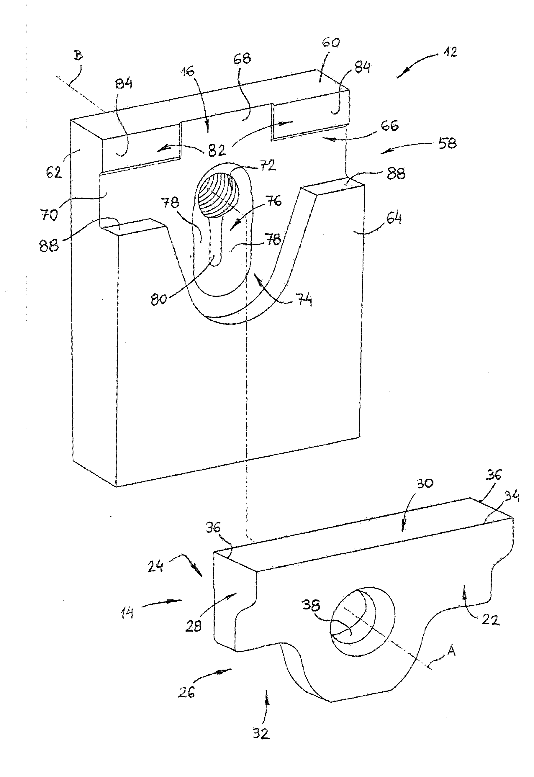
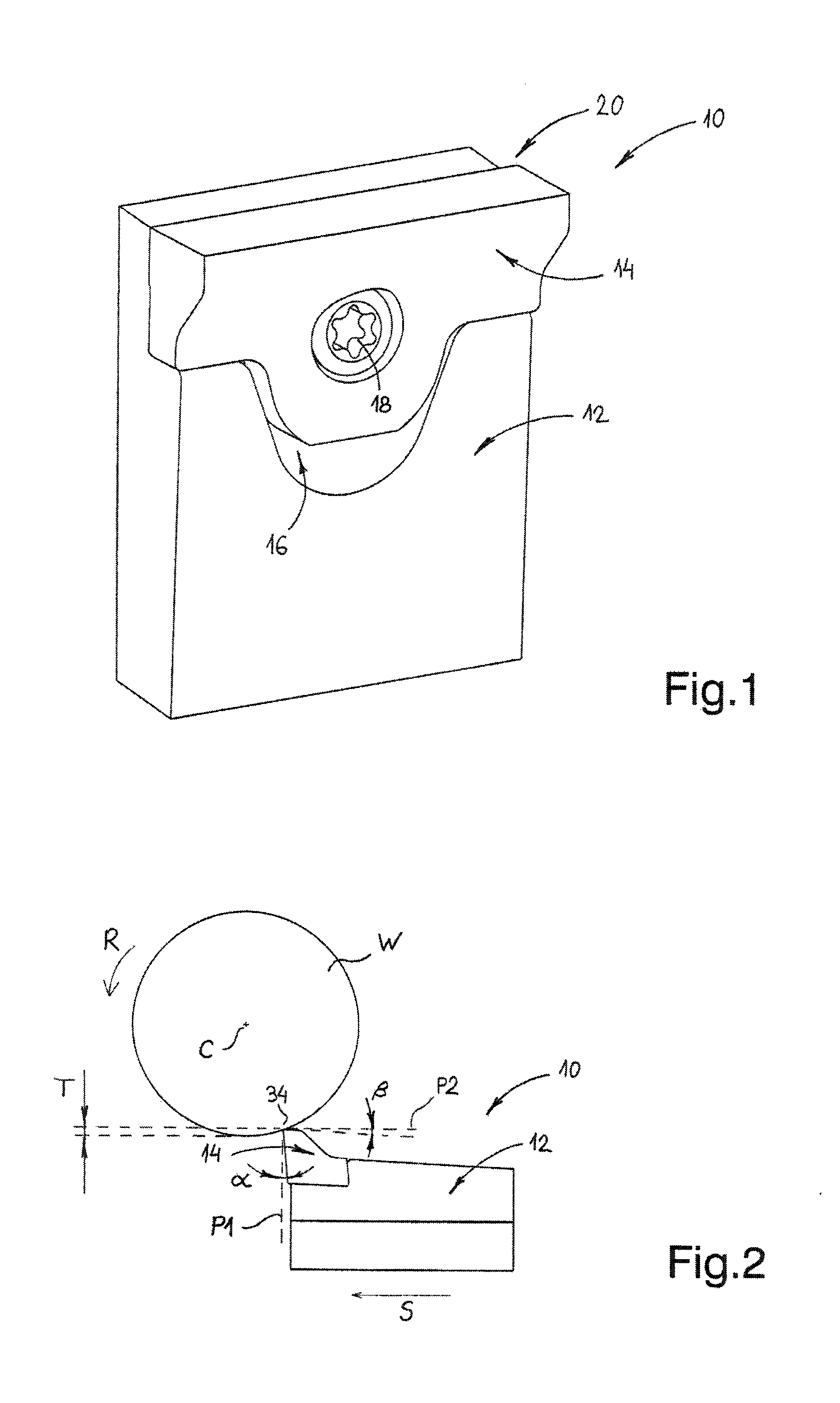
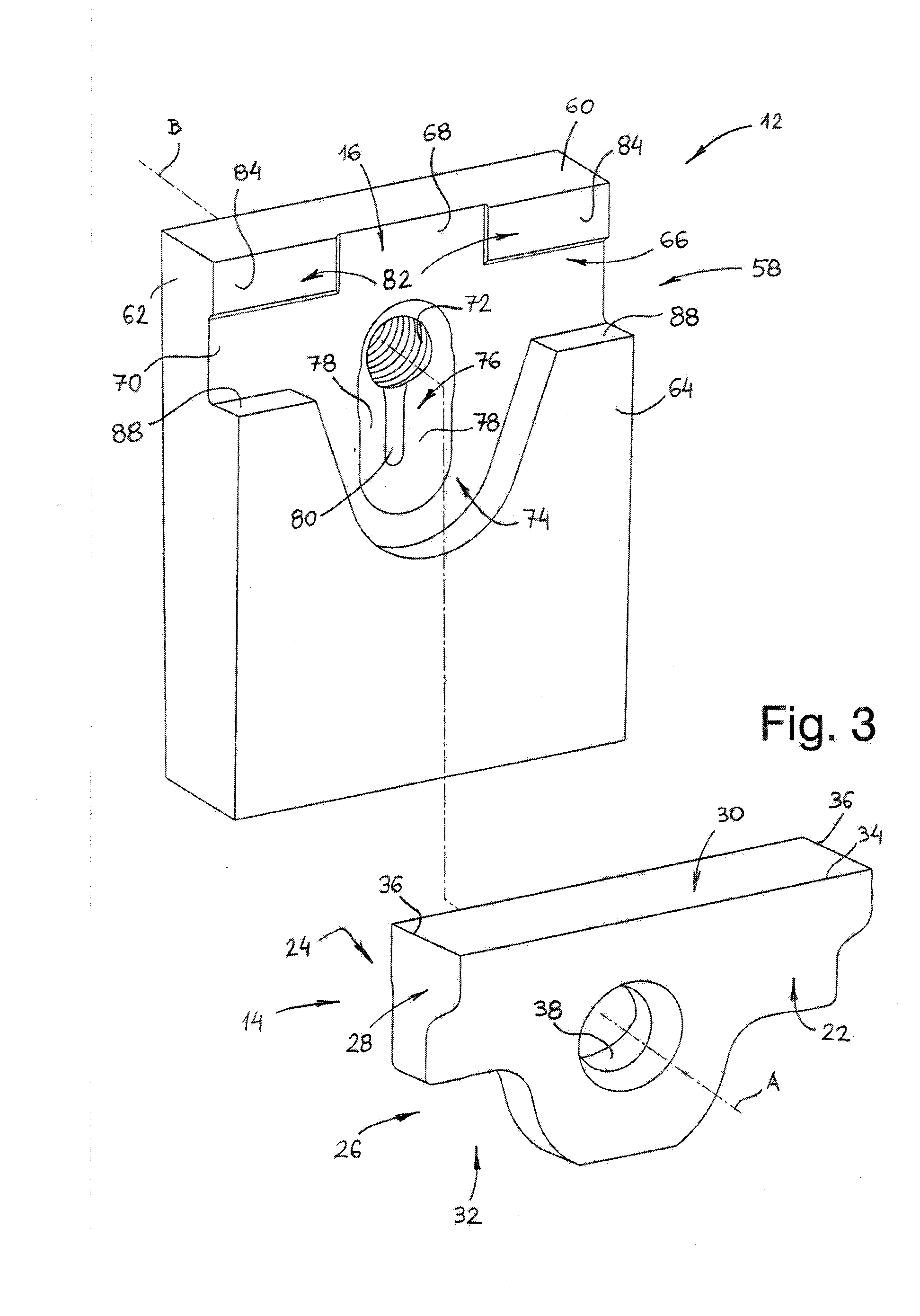
[0082]Attention is first drawn to FIG. 1 showing a preferred embodiment of a cutting portion of a cutting tool 10 in accordance with the present invention. The cutting tool 10 is designed to operate as a shaving tool. Nevertheless, the cutting tool 10 may be used for other cutting operations such as grooving, turning and slot milling. The cutting tool 10 comprises an insert holder 12 in the form of a rectangular blade with a cutting insert 14 retained in an insert pocket 16 by means of a retaining screw 18. The cutting insert 14 is typically manufactured by form-pressing and sintering carbide powders or by injection molding techniques.

[0083]The cutting tool 10 comprises a cutting portion 20 which includes the cutting insert 14, the insert pocket 16, and the immediate vicinity of the insert holder 12 adjacent the insert pocket 16. It should be noted that directional terms appearing throughout the specification and claims, e.g. “forward”, “rear”, “upper”, “lower” etc., are used as ter...


PUM

PropertyMeasurementUnit
insert engaging angleaaaaaaaaaa
pocket engaging angleaaaaaaaaaa
abutment angleaaaaaaaaaa

Abstract

A cutting tool has a cutting insert retained within an insert pocket of an insert holder by a retaining screw. Spaced apart first insert rear abutment surfaces abut spaced apart first pocket rear abutment surfaces, a second insert rear abutment surface abuts a second pocket rear abutment surface, and spaced apart insert lower abutment surfaces abut spaced apart pocket lower abutment surfaces. The cutting insert has a first dimension taken between extremities of the insert side surfaces, a second dimension taken between extremities of the insert upper and lower surfaces, and, a fourth dimension taken between the insert lower abutment surfaces and the insert upper surface. The size ratio between the fourth dimension and the second dimension is in the range of 0.2 to 1, and, preferably, in the range of 0.55 to 0.6. The size ratio between the first dimension and the second dimension is in the range of 1 to 2.

Description

FIELD OF THE INVENTION[0001]The present invention relates to cutting tools of the type in which a cutting insert is retained in an insert pocket of an insert holder by means of a retaining screw for performing a shaving operation.BACKGROUND OF THE INVENTION[0002]In cutting tools for grooving, turning or parting-off, and in cutting tools for rotary slot cutting, a cutting insert is often retained in an insert pocket between two generally opposing jaws. In these tools, chips flowing from the cutting insert's cutting edge along its rake surface during a cutting operation may engage the jaw adjacent the rake surface and subject it to considerable abrasive wear. This disadvantageous effect will in time reduce the jaw's ability to retain the cutting insert within the insert pocket.[0003]One solution which significantly overcomes this disadvantageous effect is disclosed in U.S. Pat. No. 5,947,648 to Friedman et al. A tool holder includes a holder blade having an upper jaw and a base jaw wh...

Claims


Application Information

Patent Timeline
Patent Type & Authority Applications(United States)
IPC IPC(8): B23P15/28
CPCB23B27/04B23B27/1622B23B2200/083B23B2200/125B23B2200/161Y10T407/2274B23B2205/12Y10T407/28Y10T407/2276Y10T407/116B23B2200/28
Inventor HECHT
Owner ISCAR LTD
Why Eureka
Try Eureka