Ember-resistant and flame-resistant roof ventilation system

Active Publication Date: 2009-11-19
ODANIELS LLC
View PDF111 Cites 36 Cited by
  • Summary
  • Abstract
  • Description
  • Claims
  • Application Information

AI Technical Summary

Benefits of technology

[0016]In accordance with another aspect, a roof vent is provided. The roof vent comprises a first vent member comprising a first opening that permits air flow between a region below a roof and a region above the first vent member. The roof vent also comprises a second vent member adapted to be in fluid communication with the region above the first vent member. The second vent member comprises a second opening permitting air flow between regions above and below the second vent member. At least one of the first and second vent members includes a fire-resistant mesh material that substantially prevents the ingress of floating embers through the first opening or the second openin

Problems solved by technology

In addition, increased ventilation in an attic space tends to reduce the humidity within the attic, which can prolong the life of lumber used in the building's framing and elsewhere by diminishing the incidence of mold and dry-rot.
In many areas, buildings are at risk of exposure to wildfires.
These embers can travel, airborne, up to one mile or more from the initial location of the wildfire, which increases the severity and scope of the wildfire.
One way wildfires can damage buildings

Method used


Image

  • Ember-resistant and flame-resistant roof ventilation system
  • Ember-resistant and flame-resistant roof ventilation system
  • Ember-resistant and flame-resistant roof ventilation system

Examples


Embodiment Construction

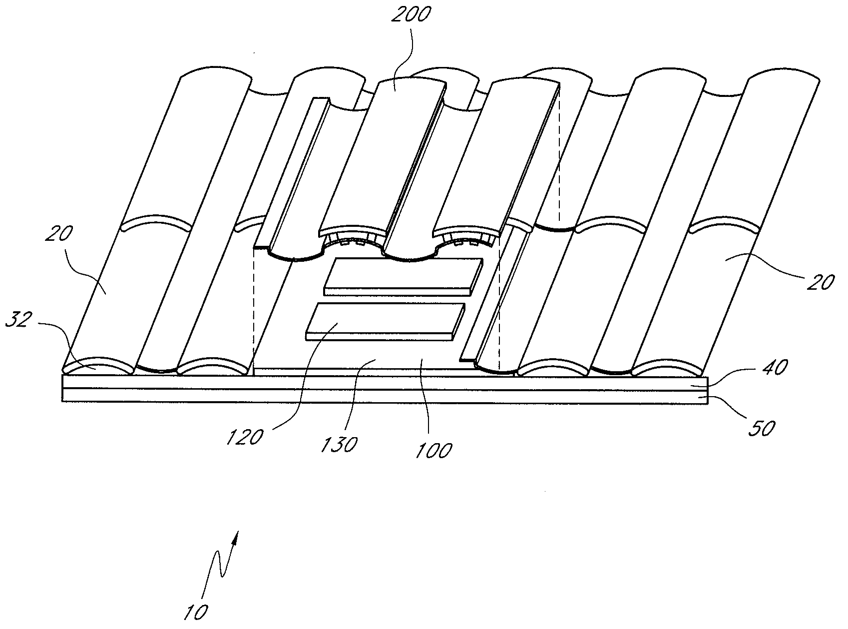
[0053]FIG. 1 is a schematic perspective view of a section of a roof including one embodiment of a roof ventilation system 10 with an ember and / or flame impedance structure. In particular, a two-piece vent system 10 is shown including a first vent member 100 and a second vent member 200. Examples of two-piece vent systems are described in U.S. Pat. Nos. 6,050,039 and 6,447,390, which are incorporated herein by reference in their entireties. With reference to FIG. 1, the first vent member 100 is sometimes referred to as a “subflashing” or “primary vent member,” and the second vent member 200 is sometimes referred to as a “vent cover” or “secondary vent member.” The second vent member 200 can rest upon the first vent member 100. In other embodiments, the second vent member 200 can engage surrounding roof tiles without contacting the first vent member 100. In such embodiments, the second vent member 200 may or may not be positioned above the first vent member 100, as described in furthe...


PUM


Abstract

This application relates to ventilation systems, more particularly to roof ventilation systems that help to protect buildings against fires. The roof vent has an ember impedance structure that impedes the entry of flames and embers or other floating burning materials while still permitting sufficient air flow to adequately ventilate a building. Several configurations of vents employing baffle members and fire-resistant mesh material are described, which can substantially prevent the ingress of floating embers and flames.

Description

CROSS-REFERENCE TO RELATED APPLICATIONS[0001]This application claims priority as a non-provisional of U.S. Provisional Patent Application No. 61 / 052,862, filed May 13, 2008, the entirety of which is incorporated herein by reference.BACKGROUND OF THE INVENTION[0002]1. Field of the Invention[0003]This invention relates to ventilation systems, more particularly to roof ventilation systems that help to protect buildings against fires.[0004]2. Description of the Related Art[0005]Ventilation of a building has numerous benefits for both the building and its occupants. For example, ventilation of an attic space can prevent the attic's temperature from rising to undesirable levels, which also reduces the cost of cooling the interior living space of the building. In addition, increased ventilation in an attic space tends to reduce the humidity within the attic, which can prolong the life of lumber used in the building's framing and elsewhere by diminishing the incidence of mold and dry-rot. M...

Claims


Application Information

Patent Timeline
IPC IPC(8): F24F7/02
CPCE04D2001/309F24F2011/0095F24F7/02F24F2221/30F24F11/33A62C3/14F24F11/0001E04D13/17F24F13/082
Inventor DANIELS, GREGORY S.
Owner ODANIELS LLC
Why Eureka
Try Eureka