Scanning aperture ion beam modulator

a technology of ion beam and aperture beam, which is applied in the direction of beam deviation/focusing by electric/magnetic means, instruments, and therapy, etc., can solve the problems of requiring the construction of special compensators, fast and yet less precise, and inconvenient treatment, so as to reduce or eliminate the need for custom compensators. , the effect of increasing the treatment speed

Active Publication Date: 2009-11-26
WISCONSIN ALUMNI RES FOUND
View PDF48 Cites 13 Cited by
  • Summary
  • Abstract
  • Description
  • Claims
  • Application Information

AI Technical Summary

Benefits of technology

[0010]The present invention provides the benefit of a scanning pencil beam while greatly increasing treatment speed. This is done by using a beam modulator that takes an area beam (as opposed to a pencil beam) and effectively creates multiple independent pencil beams that may simultaneously treat the patient. The modulator may independently control both intensity and energy of each pencil beam, reducing or eliminating the need for a custom compensator.

Problems solved by technology

Further, the dose deposited by a proton beam is not uniform along the entrance path of the beam, but rises substantially to a “Bragg peak” near a point where the proton beam stops within the tissue.
This treatment approach essentially treats the entire tumor at once and, thus, is fast and yet less precise and requires the construction of a special compensator.
This approach is potentially very accurate, but because the tumor is treated in successive exposures, is slower than the first approach.
Further the small spot sizes create the risk of uneven dose placement or “cold spots” should there be patient movement between exposures.
The complexity of these techniques normally limits the treatment to a single or small number of angles about the patient.
This can reduce the level of conformity of the radiation dose to the target tumor because of this strong asymmetry of the Bragg peak of the protons.

Method used


Image

  • Scanning aperture ion beam modulator
  • Scanning aperture ion beam modulator
  • Scanning aperture ion beam modulator

Examples


Embodiment Construction

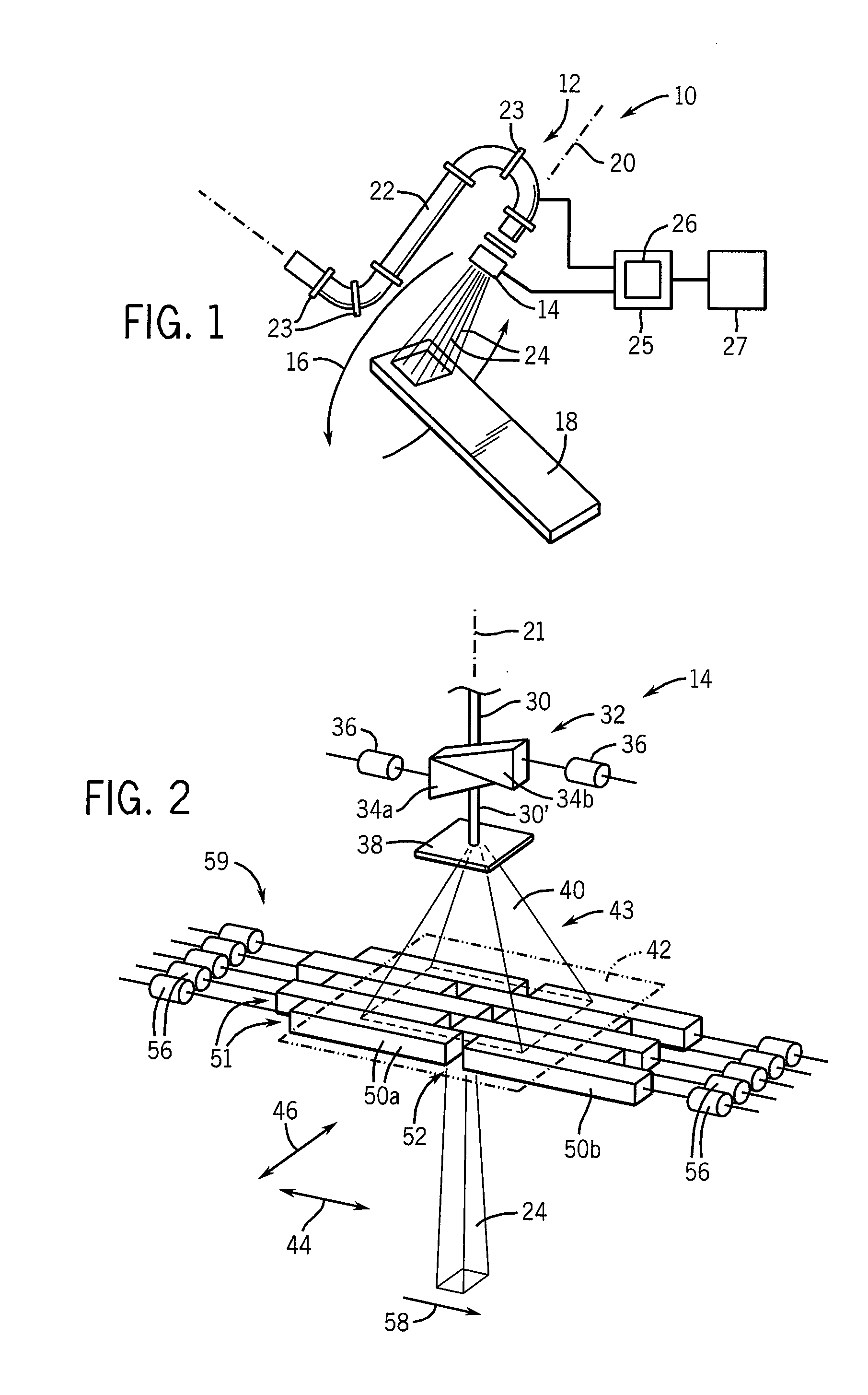
[0039]Referring now to FIG. 1, a proton therapy machine 10 may include a gantry 12 having a modulator 14, both of which may orbit 16 about a patient (not shown) who is supported on a patient support table 18.

[0040]The modulator 14 receives a source of protons from a proton source conduit 22 that may conduct protons from a synchrotron, cyclotron or the like and, by means of bending magnets 23, direct them toward the patient support table 18 at all positions within the orbit 16.

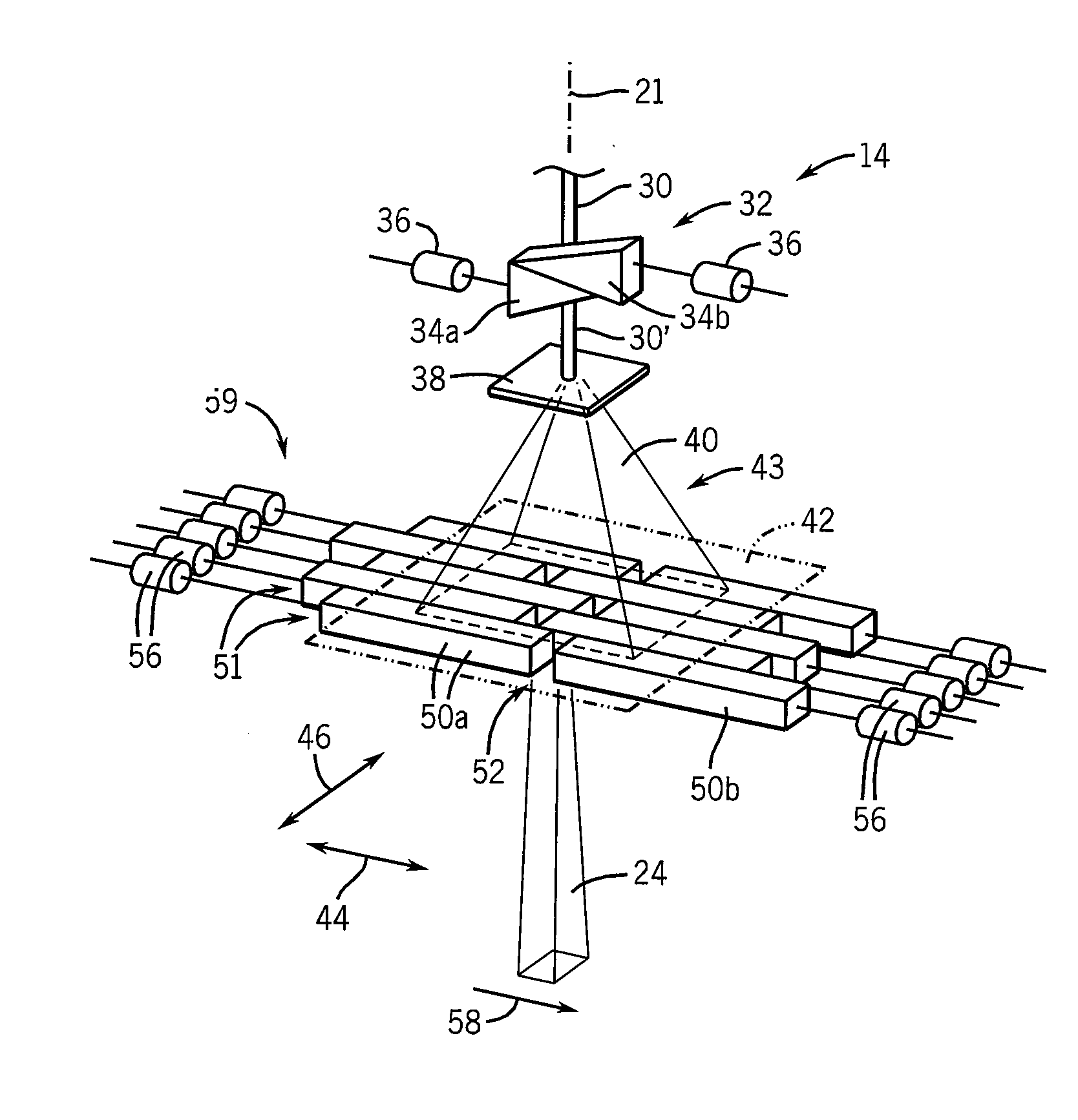
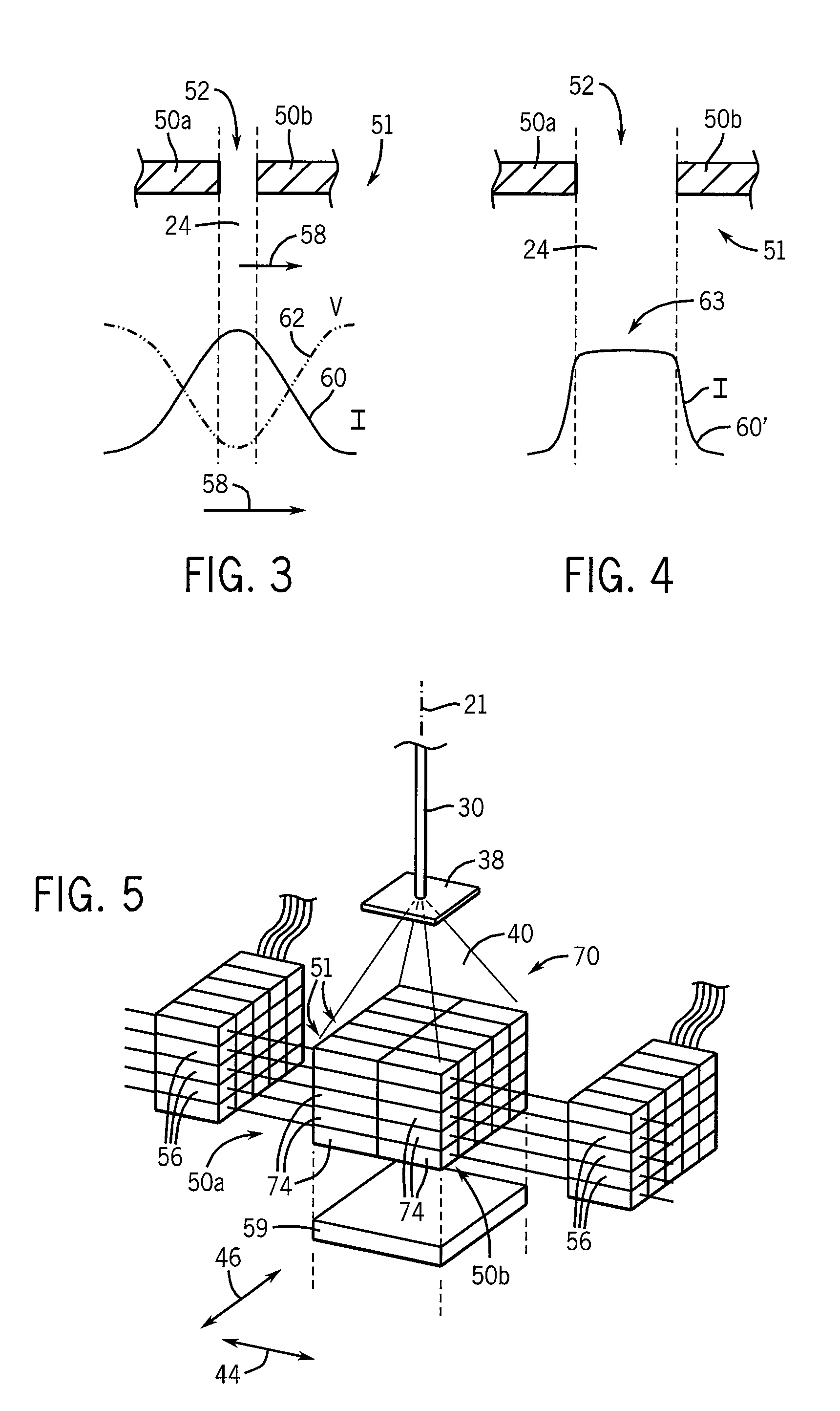
[0041]The protons from the proton source conduit 22 will generally be narrowly collimated to a pencil beam (not shown) when received by the modulator 14. The modulator 14 spreads the pencil beam into an area beam radiating along an axis 20, and individually modulates independently positionable beamlets 24 (e.g., pencil beams) in energy and intensity. The beamlets 24 are controlled by a control computer 25 communicating with the modulator 14, the control computer 25 executing a stored program 26 to provide contr...


PUM


Abstract

A modulator for ions such as protons employs multiple shutter pairs to create independently movable apertures effecting a multiple pencil beam treatment of the patient thereby increasing treatment speed by eliminating the need for a custom compensator.

Description

CROSS-REFERENCE TO RELATED APPLICATIONS[0001]This application claims the benefit of U.S. Provisional Application 60 / 891,859, filed Feb. 27, 2007, and PCT Application PCT / US2008 / 055090, filed Feb. 27, 2008, the disclosures of which are incorporated herein by reference.STATEMENT REGARDING FEDERALLY SPONSORED RESEARCH OR DEVELOPMENT[0002]This invention was made with United States government support awarded by the following agency: NIH CA088960. The United States has certain rights in this invention.BACKGROUND OF THE INVENTION[0003]The present invention relates to radiation therapy systems using ions, such as protons, for the treatment of cancer and the like and, in particular, to a system providing improved modulation of an ion beam.[0004]External beam radiation therapy may treat a tumor within the patient by directing high-energy radiation in one or more beams toward the tumor. Recent advanced external beam radiation systems, for example, as manufactured by Tomotherapy, Inc., treat a ...

Claims


Application Information

Patent Timeline
Patent Type & Authority Applications(United States)
IPC IPC(8): H01J3/14A61N5/00
CPCA61N5/10A61N5/103G21K1/046A61N2005/1095A61N2005/1087
Inventor WESTERLY, DAVID C.MACKIE, THOMAS R.FLYNN, RYAN T.
Owner WISCONSIN ALUMNI RES FOUND
Why Eureka
Try Eureka