
System and method for producing a tangible object

a tangible object and system technology, applied in the field of tangible three-dimensional objects, can solve the problems of long relatively time-consuming, and the inability to form a new resin layer in a relatively long time, so as to achieve faster production, reduce the period of time required to produce objects, and achieve the effect of fast construction

Active Publication Date: 2009-11-26
NEDERLANDSE ORG VOOR TOEGEPAST-NATUURWETENSCHAPPELIJK ONDERZOEK (TNO)
View PDF13 Cites 24 Cited by
  • Summary
  • Abstract
  • Description
  • Claims
  • Application Information

AI Technical Summary

Benefits of technology

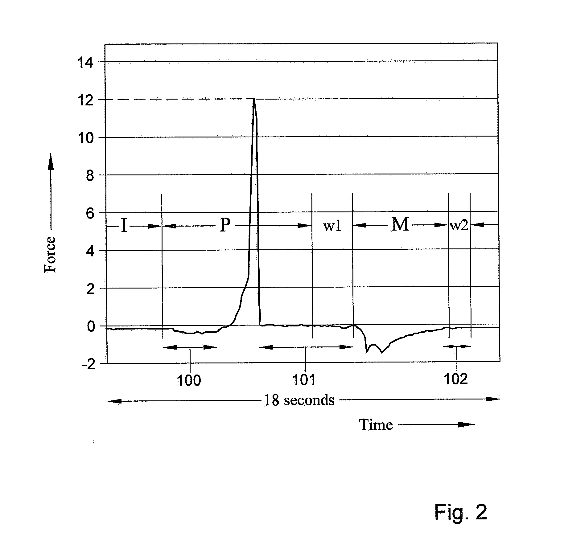
[0009]The object can be produced faster, because a suitable period or moment in time for an action in the production can be determined from the force exerted on the reference platform or the solid or from a parameter related to the force. Hence, there is no need to use the same preset period or moment for all layers, and the period of time required to produce a layer can be adapted to a specific layer. Accordingly, the period of time required to produce the object can be reduced. A second reason that the object can be built faster is, that the relative speed of movement between the carrier platform and the reference platform can be increased and optimized to suit the specific geometry and material of the object that is built.

Problems solved by technology

However, a disadvantage of SLA is the long period of time required to produce the object.
Especially when large surfaces are required, this is relatively time consuming.
Another shortcoming of the SLA is the long time for the resin surface to settle and straighten after lowering the object below the liquid level, and hence forming a new resin layer takes a relatively long time.
However, a common disadvantage of both the SLA and the Perfactory, is that it takes a relatively long period of time to produce the object.

Method used


Image

  • System and method for producing a tangible object
  • System and method for producing a tangible object
  • System and method for producing a tangible object

Examples


Embodiment Construction

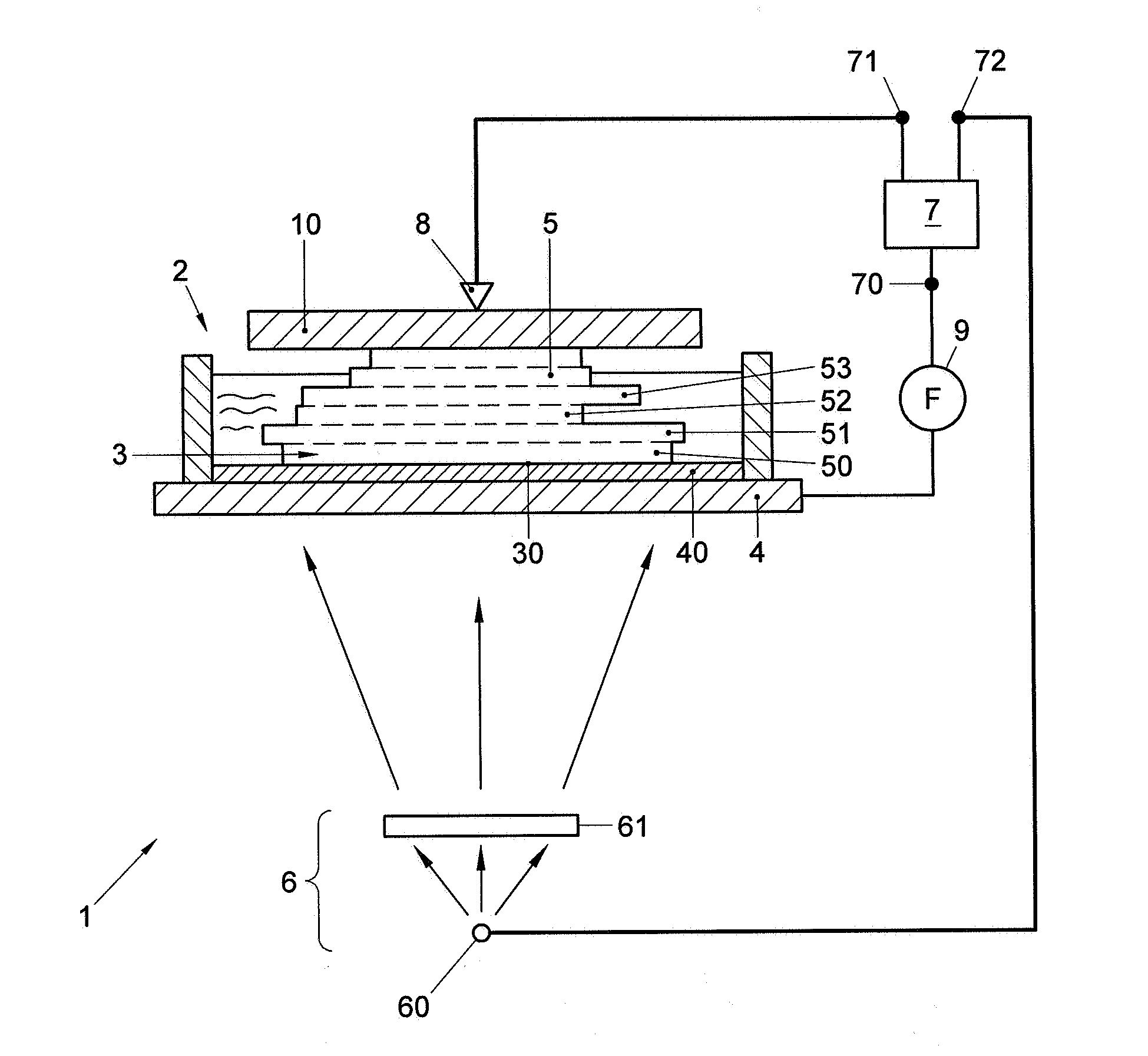
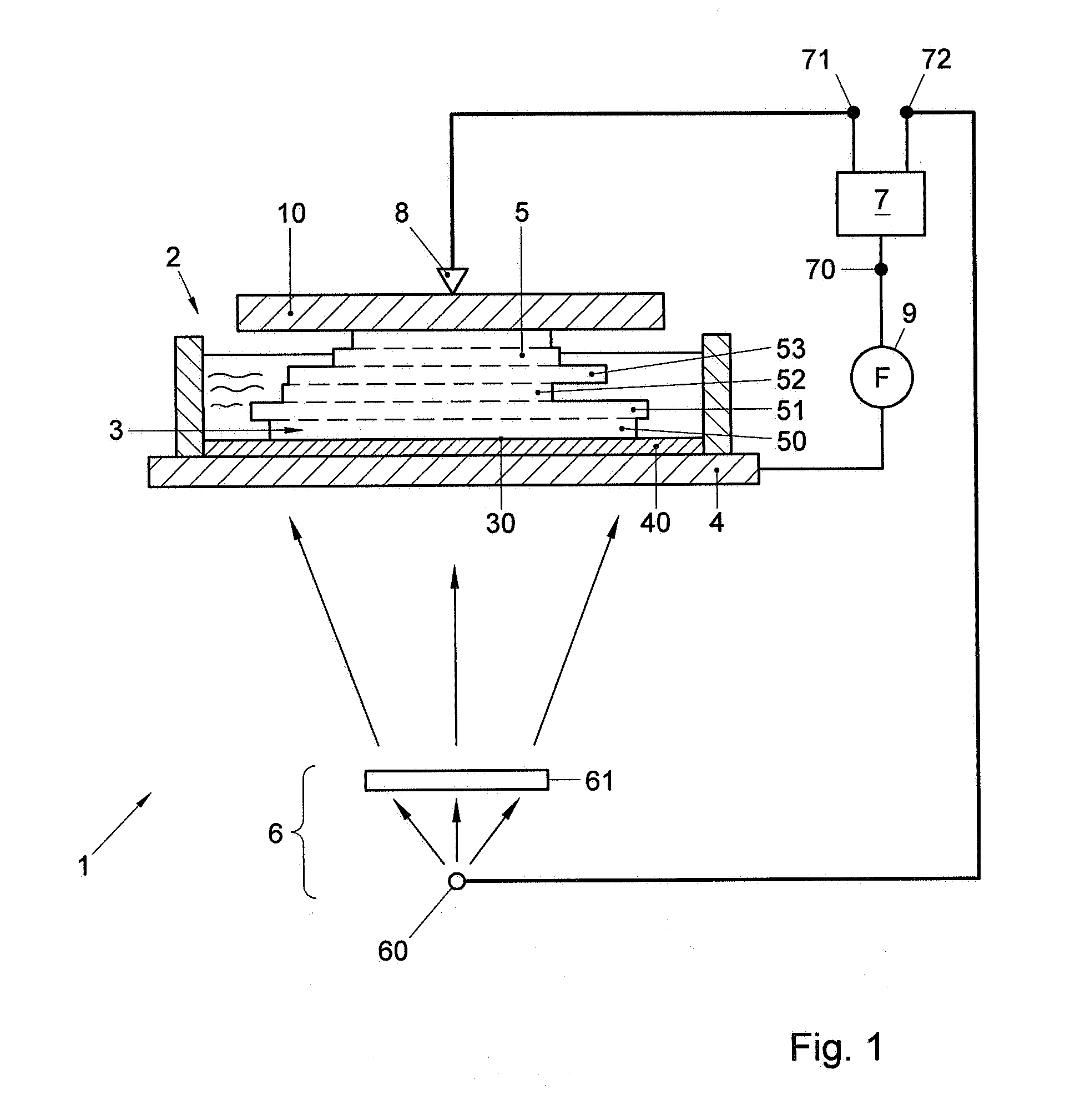
[0016]FIG. 1 shows an example of a system 1, for producing a tangible object. In this figure, the object 5 is shown while being produced. The tangible object 5 may for example be a prototype or model of an article of manufacture or other suitable type of object. The system 1 may, as shown in FIG. 1, include a basin 2 in which a liquid can be provided. In the example of FIG. 1, the basin 2 includes a space 3 which can be filled with the liquid, to form a layer of fluid which can be transformed into a solid layer. At least one side 30 of the space 3 is at least partially defined by a reference platform 4. In this example the reference platform 4 defines the bottom side of the space 3.

[0017]However, it is also possible that the reference platform 4 defines the top side of the space 3. In this example, the reference platform 4 includes an anti-stick layer 40, such as a rubber-like layer or a silicon layer, which forms a wall of the space and reduces the sticking of the layer 50 to the r...


PUM

PropertyMeasurementUnit
timeaaaaaaaaaa
forceaaaaaaaaaa
areaaaaaaaaaaa

Abstract

A system for producing a tangible object. The system has a space which can be filled with a fluid. A reference platform at least partially defines at least one side of the space. The system further has a phase-transformer which can form a layer of the object by selectively transforming the fluid into a solid in a predetermined area of the space. An actuator can separate the layer from the reference platform by moving the layer relative to the reference platform or vice versa. The system has a controller connected with an actuator control output to the actuator and / or with a transformer control output to the phase transformer. The controller can control the production of the object based on a determined value of the force exerted on the reference platform or the solid or of a parameter related to the force.

Description

FIELD AND BACKGROUND OF THE INVENTION[0001]The invention relates to a system and a method for producing a tangible three-dimensional object, such as a tangible model.[0002]It is known in the field of Layered Manufacturing Technology (LMT)—often referred to as Rapid Prototyping (RP) or Rapid Manufacturing (RM)—to produce a tangible object. Rapid Prototyping (RP) and Rapid Manufacturing (RM), are called “Rapid” since they do not require a mould to be designed and manufactured.[0003]An example of a LMT technique is the Stereo Lithography Apparatus (SLA). In SLA an object is produced by curing successive layers of a liquid resin in a suitable shape and size. The SLA includes a laser, which is used to cure a layer in the desired shape and size by moving the laser beam over the surface of a bath of photocurable resin. The movement of the beam over the surface is controlled to correspond to a CAD / CAM slice pattern of a designed 3D digital model of the object to be produced. Accordingly, th...

Claims


Application Information

Patent Timeline
Patent Type & Authority Applications(United States)
IPC IPC(8): B29C67/00
CPCB29C67/0066B29C67/0062B29C64/124B29C64/135B29C64/40G05B19/237B23Q17/20B29C45/766G05B19/19G05B19/404B29C45/76G05B19/4099B29C45/80G05B19/235B29C64/393
Inventor MAALDERINK, HERMAN HENDRIKUSMICHELS, JASPER JOOSTBOOT, RONALDUS JACOBUS JOHANNES
Owner NEDERLANDSE ORG VOOR TOEGEPAST-NATUURWETENSCHAPPELIJK ONDERZOEK (TNO)
Learn More