
Input arrangement for electronic devices

a technology of electronic devices and inputs, applied in the field of input arrangements for electronic devices, can solve the problems of physical damage to users, muscle, joint and nerve damage to users, damage to nerves and muscles, etc., and achieve the effect of reducing stress and increasing input efficiency

Inactive Publication Date: 2009-11-26
JACOB EMIL
View PDF2 Cites 10 Cited by
  • Summary
  • Abstract
  • Description
  • Claims
  • Application Information

AI Technical Summary

Benefits of technology

[0010]This invention is therefore directed to a class of new ergonomic electronic input arrangements for handheld electronic devices which reduce the stress associated with repeated movement and increase input efficiency. Included are input arrangements for a computer mouse, and for various handheld electronic keyboard devices, such as cell phones and other portable data entry devices.
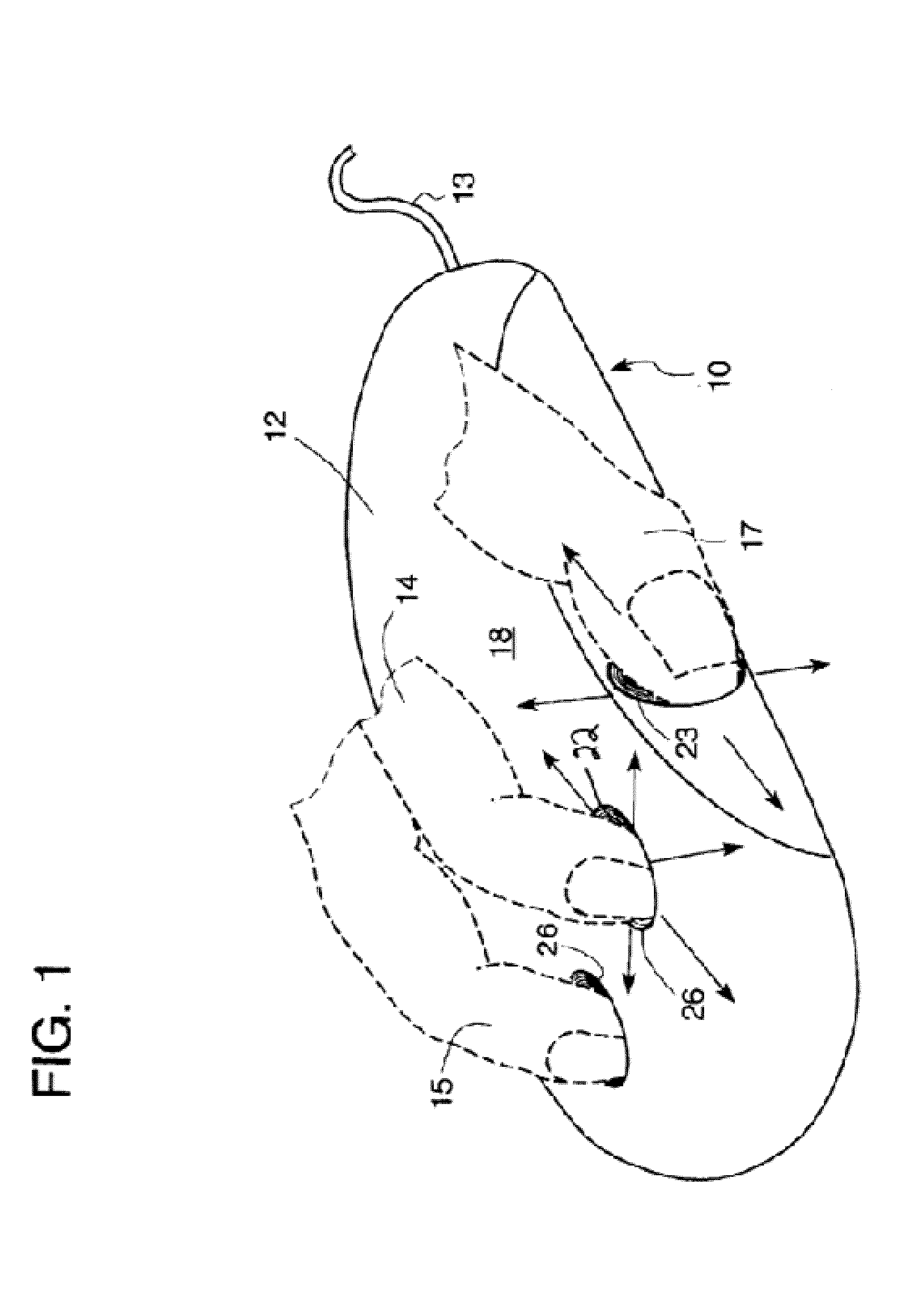
[0011]There is described a new form of computer cursor control device in which the activation surfaces are designed to allow the fingers and thumb of the user to effect commands by means of non-repetitive motion as compared to current devices. Specifically, sensors are associated with the fingers and thumb which sense motion in not only the downward direction, as generally used in current devices, but also in forward backward and side directions to carry out the same command. The resulting ability of the user to vary the points of pressure and other stresses onto different surfaces of the digits and corresponding nerves and muscles serves to relieve discomfort and pain.
[0012]The handheld keyboard input arrangement similarly to alleviates (in a Blackberry-like device, for example) overuse and damage to the thumbs and associated nerves and muscles. This arrangement includes provision of input keys or an entire keyboard on the back of the device so that both the thumbs and fingers may be utilized in entering data. This arrangement may incorporate the same type of individual key input for each finger as was disclosed above for use in the mouse / cursor control. The essence of such an arrangement includes the provision of positioning input sensors or switches in such a way relative to each finger and thumb that several keys may be activated by movement of the finger in various directions. This allows for different motions of the digits of a user to effect a common input or command to thereby distribute the stress attendant to executing an input / command over different digits or the same digit in a different way. Alternatively, by permitting small but differently directed motions to be detected from a single digit, the arrangement enhances the efficiency for entering commands and data in a hand held electronic device.

Problems solved by technology

This need for using the same physical motion, and only that motion, to generate the same command results in muscle, joint and nerve damage to the user, such as carpal tunnel syndrome, among other conditions.
It is used more than any other and results in the aforementioned physical damage to the user.
However, this technique is associated with significant stress to the thumbs, resulting in damage to nerves and muscles and is the source of great discomfort to many users.

Method used


Image

  • Input arrangement for electronic devices
  • Input arrangement for electronic devices
  • Input arrangement for electronic devices

Examples


Embodiment Construction

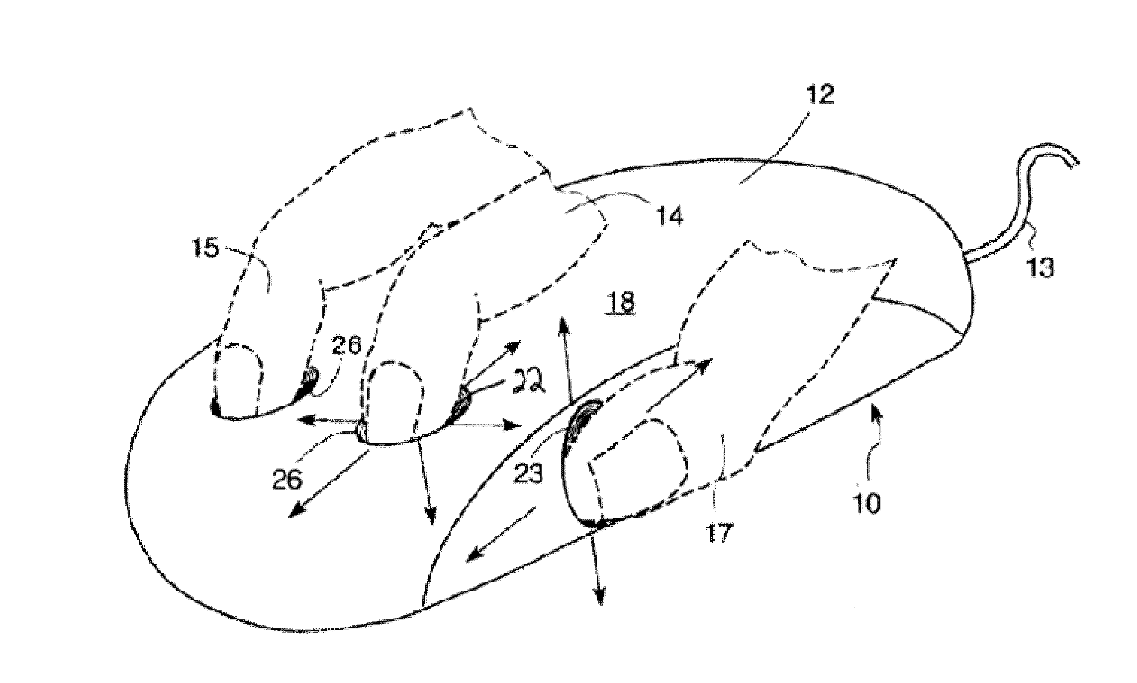
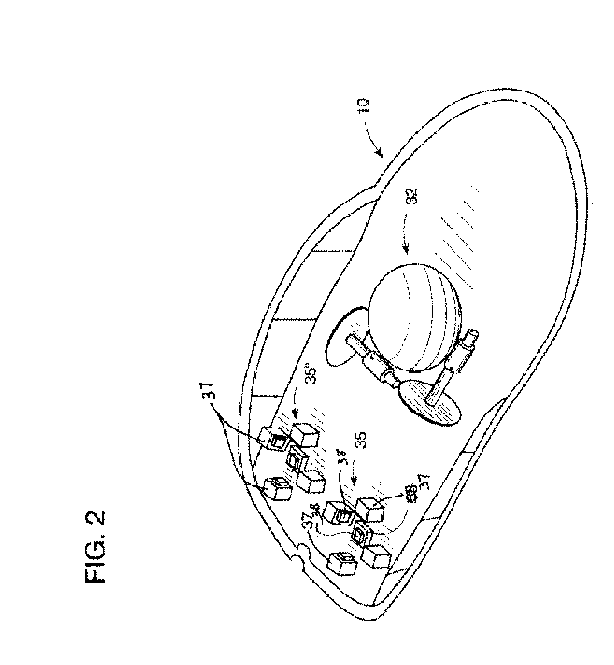
[0027]The new ergonomic input arrangements of this invention will now be described in detail with reference to the drawings. The computer cursor control of the invention, as implemented in a generally off-the-shelf mouse, is best understood by reference to FIGS. 1 and 2. Referring to FIG. 1, there is shown a mouse 10 having a housing 12 and a cable 13 for coupling the mouse to a computer (not shown). The mouse 10 is designed for operation by the hand of a user, shown in dotted lines in FIG. 1, including index finger 14, middle finger 15 and thumb 17. The housing 12 includes a generally ovulate-shaped top surface 18 on which the palm of the user rests during operation of the mouse. The surface 18 includes suitably shaped elongated openings 21, 22 into which the tips of the user's fingers extend, and a similar opening 23 in the side wall of the housing into which the tip of the user's thumb 17 extends. The fingers 14 and 15 are located directly above sensor arrangements 35, each of wh...


PUM


Abstract

A new form of input arrangement for cursor control devices or other handheld electronic devices in which the activation surfaces are designed to allow the fingers and thumb of the user to affect commands by means of ergonomic and less repetitive motion as compared to current devices. In embodiments, sensors are associated with the user's digits which sense motion in not only the downward direction, but in multiple directions. In embodiments, the cursor control device has resilient pads to further add comfort to a user. The resulting ability of the user to vary and reduce the points of pressure and other stresses onto different surfaces of the digits and corresponding nerves and muscles serves to reduce discomfort and pain resulting from current devices.

Description

CROSS-REFERENCE TO RELATED PATENT APPLICATIONS[0001]This application is a continuation in part of co-pending U.S. patent application Ser. No. 11 / 702,945, filed 5 Feb. 2007, entitled “Input Arrangements for Electronic Devices” the entire contents of which are herein incorporated by reference in their entirety. This application also claims benefit of U.S. Provisional Patent Application Ser. No. 60 / 776,223, filed 3 Feb. 2006, entitled “Ergonomic Electronic Devices” the entire contents of which are incorporated by reference in their entirety.STATEMENT REGARDING FEDERALLY SPONSORED RESEARCH OR DEVELOPMENT[0002]Not Applicable.NAMES OF PARTIES TO JOINT RESEARCH AGREEMENT[0003]Not Applicable.REFERENCE TO SEQUENCE LISTING, A TABLE, OR A COMPUTER PROGRAM LISTING COMPACT DISC APPENDIX[0004]Not Applicable.BACKGROUND OF THE INVENTION[0005]Current input devices designed for use with computers, commonly referred to as mice, are increasingly used to carry out commands in using the most modern opera...

Claims


Application Information

Patent Timeline
IPC IPC(8): G06F3/033
CPCG06F1/1626G06F2203/0333G06F3/03543G06F3/0202
Inventor JACOB, EMIL
Owner JACOB EMIL
Learn More