
Lighting fixture

a technology for lighting fixtures and led fixtures, applied in the field of lighting fixtures, can solve the problems of increasing the cost of upgrading an existing led fixture with more efficient leds, and increasing the cost of upgrading. the effect of upgrading

Inactive Publication Date: 2009-11-26
ABL IP HLDG
View PDF103 Cites 159 Cited by
  • Summary
  • Abstract
  • Description
  • Claims
  • Application Information

AI Technical Summary

Benefits of technology

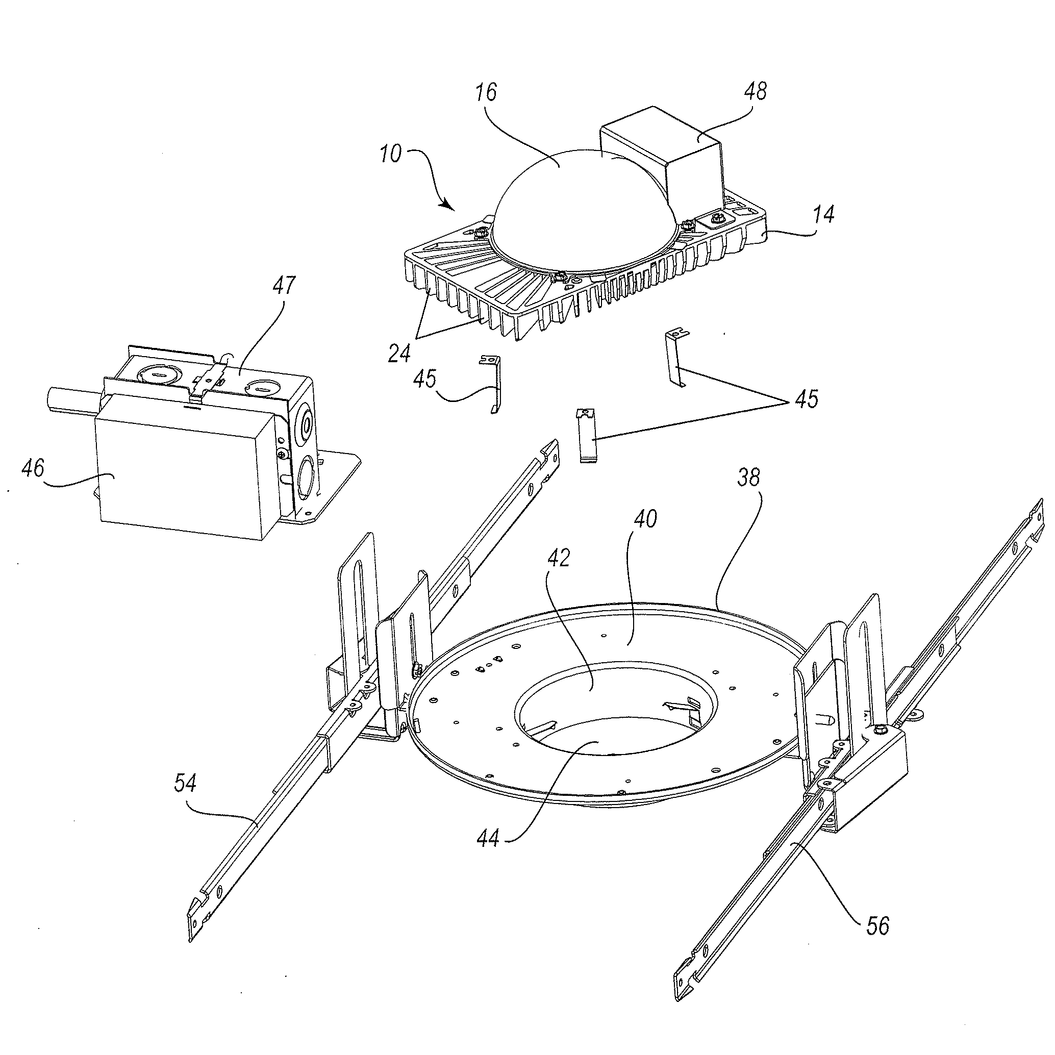
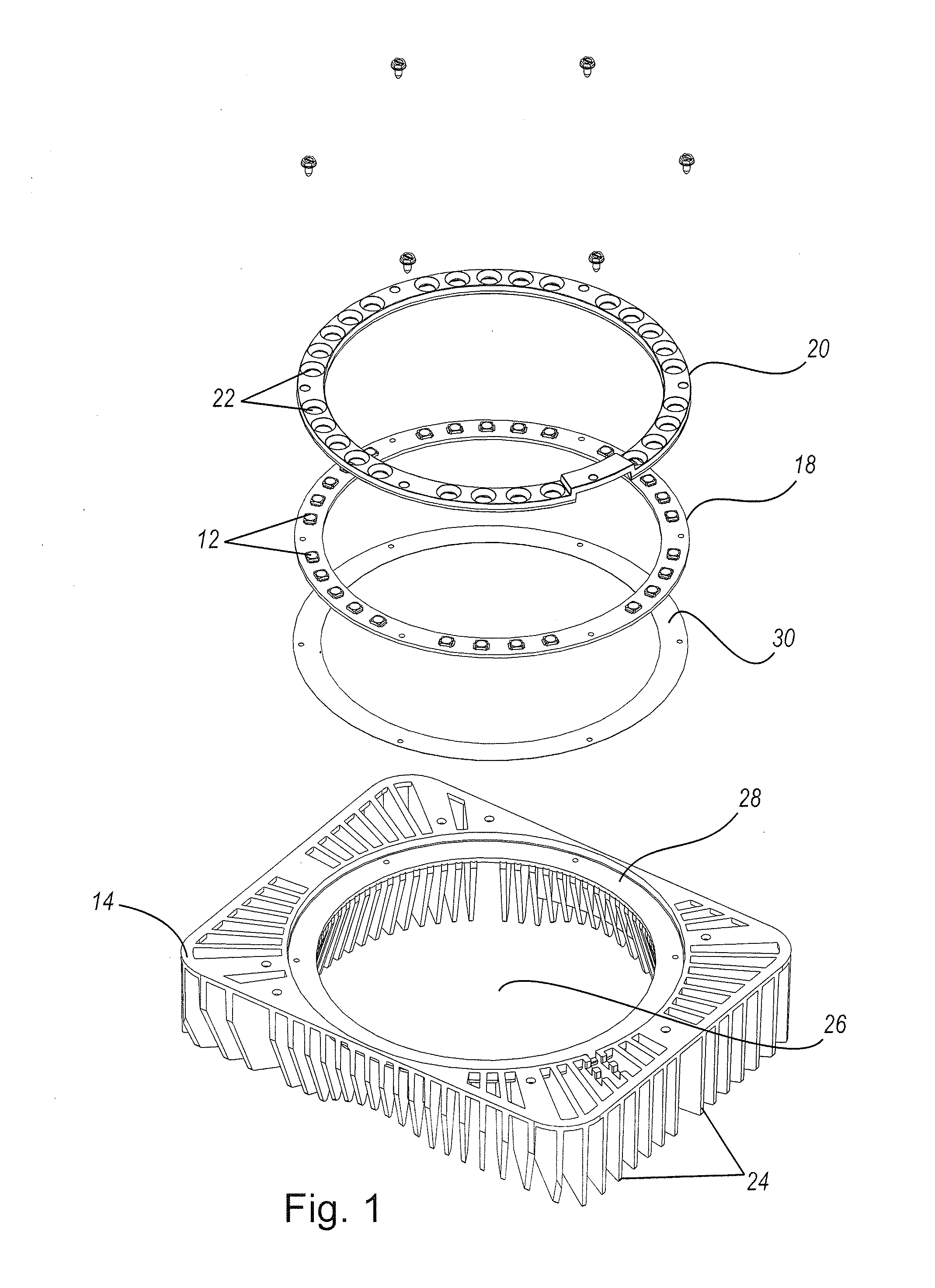
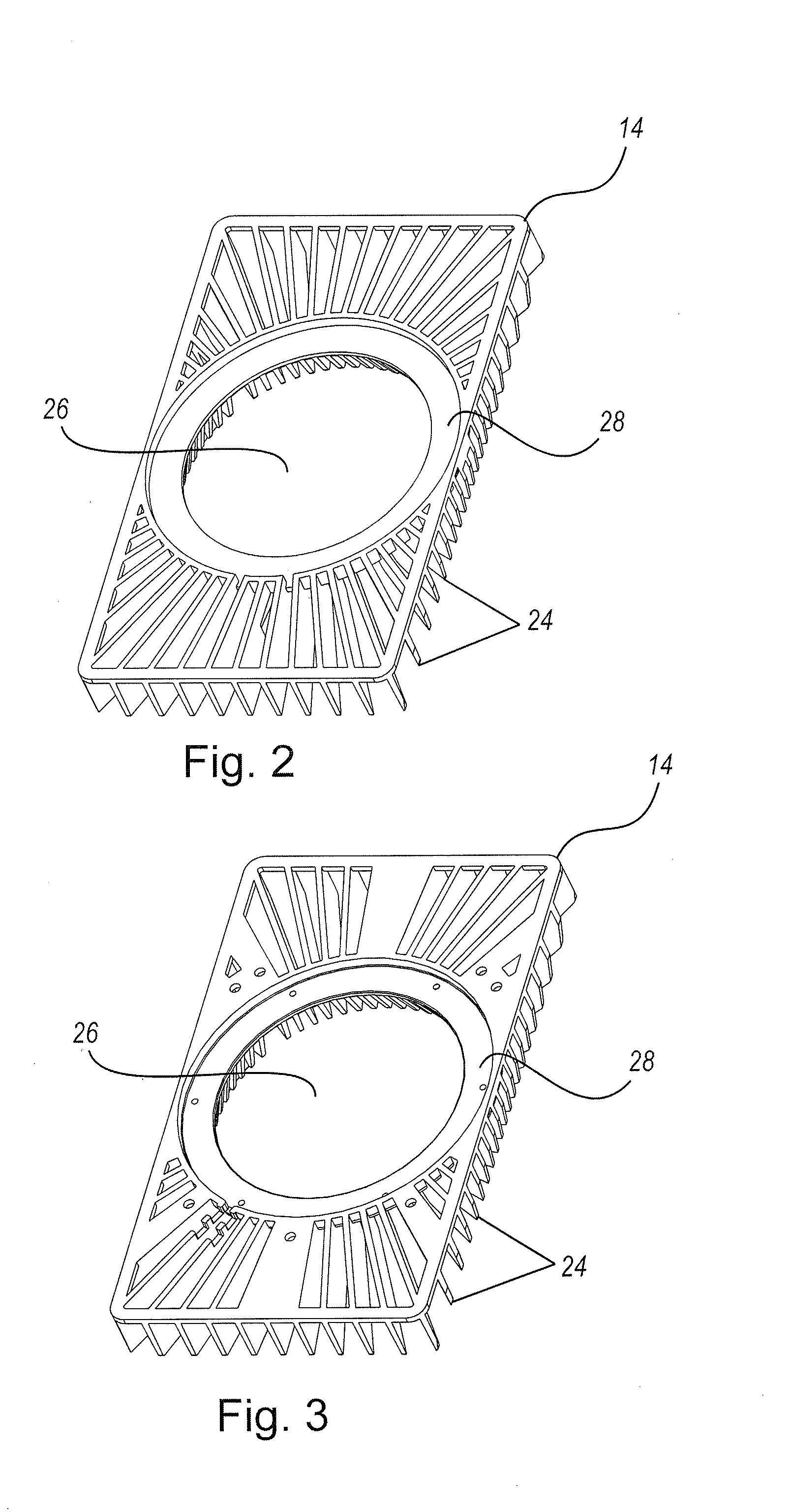
[0005]Embodiments of the invention provide lighting assemblies for recessed lighting, but may be used in lighting fixtures of any type. In one embodiment, lighting assemblies include a plurality of light sources, such as light emitting diodes, a heat sink, and a reflector. Light emitting diodes may be mounted on a printed circuit board, which is then mounted on the heat sink. The reflector is positioned over the printed circuit board and also mounted to the heat sink. The reflector preferably has an inner surface with an extremely high surface reflectivity. An outer surface of the reflector may comprise a heat sink to further enhance heat dissipation.
[0007]Some embodiments of the present invention enable easy upgradeability. The lighting assembly may be removed through the mounting pan aperture without un-installing the entire lighting fixture from the ceiling. After removal, an entirely new lighting assembly may be installed or the existing lighting assembly may be upgraded by replacing the circuit board with a new circuit board containing the desired light emitting diodes.

Problems solved by technology

Such bulbs are inefficient and have a relatively short lamp life.
However, in comparison to simply changing a light bulb in a conventional lighting fixture, updating an existing LED fixture with more efficient LEDs can be labor intensive and costly.
Environmental concerns, such as asbestos contamination and asbestos removal, become an issue when disturbing the ceiling.
Moreover, the area above the ceiling collects dirt and dust, which can dislodge during LED replacement and thereby increase the time and cost of clean-up after installation.
Additionally, exposed electrical wiring is common in such areas, which creates a safety hazard for workers removing old fixtures.
Thus, consumers are reticent to invest in an LED fixture today if the LEDs will quickly become obsolete and they cannot easily replace them with more efficient LEDs.

Method used


Image

  • Lighting fixture
  • Lighting fixture
  • Lighting fixture

Examples


Embodiment Construction

[0005]Embodiments of the invention provide lighting assemblies for recessed lighting, but may be used in lighting fixtures of any type. In one embodiment, lighting assemblies include a plurality of light sources, such as light emitting diodes, a heat sink, and a reflector. Light emitting diodes may be mounted on a printed circuit board, which is then mounted on the heat sink. The reflector is positioned over the printed circuit board and also mounted to the heat sink. The reflector preferably has an inner surface with an extremely high surface reflectivity. An outer surface of the reflector may comprise a heat sink to further enhance heat dissipation.

[0006]The lighting assembly may be installed in a recessed lighting fixture or other suitable lighting installation. In these embodiments, the lighting assembly is connected to a mounting pan, which includes a base portion, a draw down, and an aperture. The lighting assembly is positioned over the mounting pan aperture. A trim piece, wh...


PUM


Abstract

Embodiments of the invention provide lighting assemblies for installation in lighting fixtures. Lighting assemblies include at least one light source, at least one heat sink, and at least one reflector. Other embodiments of the lighting assembly may also include an outer surface of the reflector comprising a heat sink. In some embodiments, it may be desirable to direct light toward a wall. In those situations, a wall wash trim may be included. The lighting assemblies disclosed herein may be modular and thus replaced without having to uninstall the entire fixture. In some embodiments, a circuit board containing at least one light emitting diode in an existing lighting assembly may be replaced with another circuit board containing light emitting diodes of a different color temperature or a different color.

Description

CROSS-REFERENCE TO RELATED APPLICATIONS[0001]This application claims the benefit of U.S. Provisional Application No. 61 / 055,537, entitled “Led Dome Downlight With Circular LED Ring And Associated Heat Sink” and filed May 23, 2008, the entirety of which is incorporated herein by reference.FIELD OF THE INVENTION[0002]Embodiments of the invention relate to lighting fixtures.BACKGROUND OF THE INVENTION[0003]Traditional recessed light or down light fixtures include a metal cylinder that is mounted in the ceiling and that contains a light socket. An incandescent or fluorescent bulb is typically mounted in the light socket to provide the desired illumination. Such bulbs are inefficient and have a relatively short lamp life. Thus, efforts have been made to identify suitable alternative illumination sources for recessed lighting applications. Light emitting diodes (“LEDs”) have been identified as one alternative to traditional incandescent and fluorescent bulbs.[0004]LEDs are extremely effic...

Claims


Application Information

Patent Timeline
IPC IPC(8): F21V1/00H01J9/24
CPCF21K9/00F21S8/02F21Y2103/022F21V17/12F21V29/83F21V29/677F21V29/76F21V29/77F21V17/164F21Y2103/33
Inventor BROWN, JEFFREY ALANKING, LESLIE CHARLESCLIFTON, DAVID
Owner ABL IP HLDG
Learn More