Tap-off closure systems and methods for using the same

a technology of closure system and tape closure, which is applied in the direction of gaseous cathode, electric apparatus casing/cabinet/drawer, instruments, etc., can solve the problem that the capacity and communication rate capabilities of such equipment may exceed that provided by conventional copper wired systems

Inactive Publication Date: 2009-11-26
COMMSCOPE TECH LLC
View PDF8 Cites 47 Cited by
  • Summary
  • Abstract
  • Description
  • Claims
  • Application Information

AI Technical Summary

Problems solved by technology

The carrying capacity and communication rate capabilities of such equipment may exceed that provided by conventional copper wired systems.

Method used


Image

  • Tap-off closure systems and methods for using the same
  • Tap-off closure systems and methods for using the same
  • Tap-off closure systems and methods for using the same

Examples


Embodiment Construction

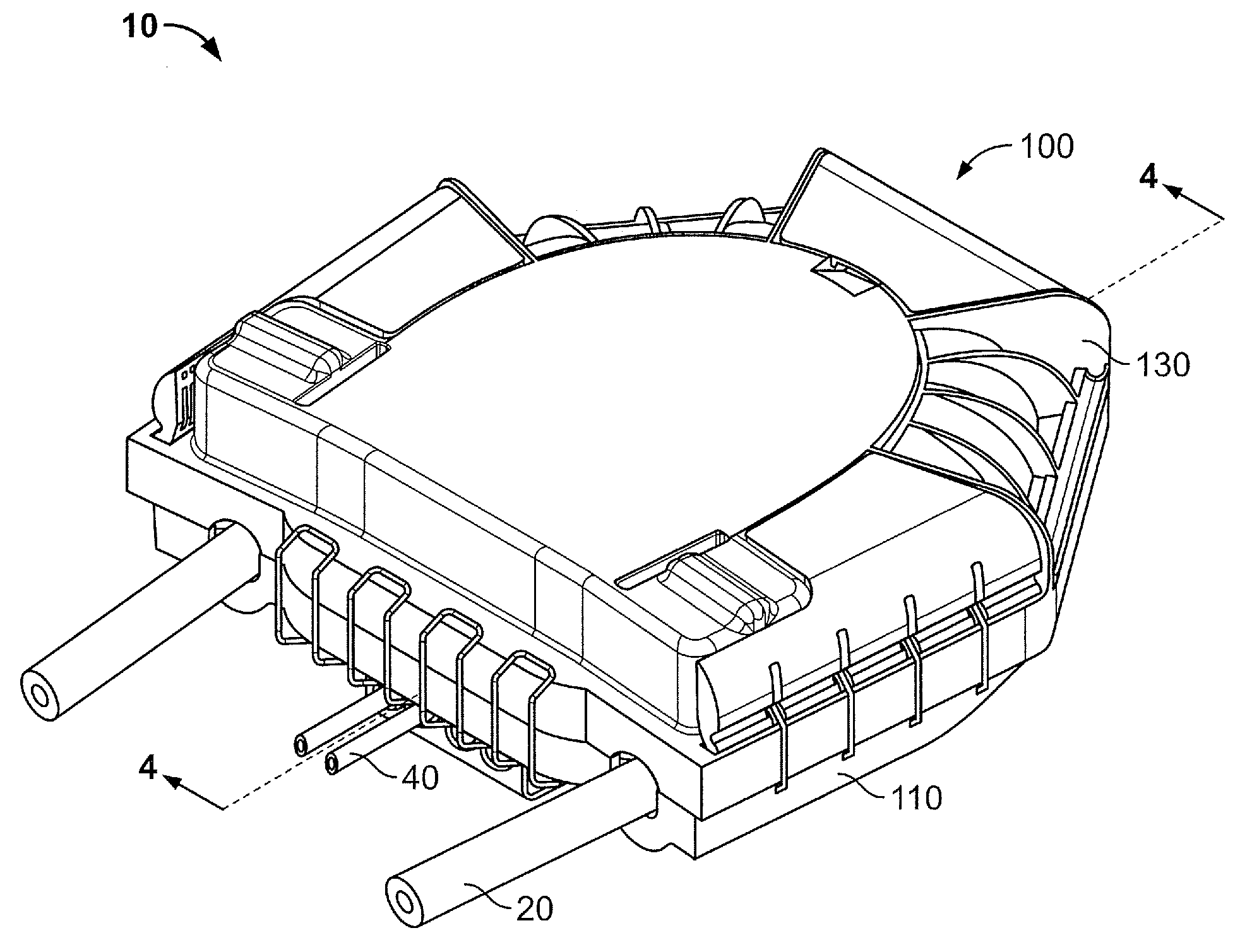
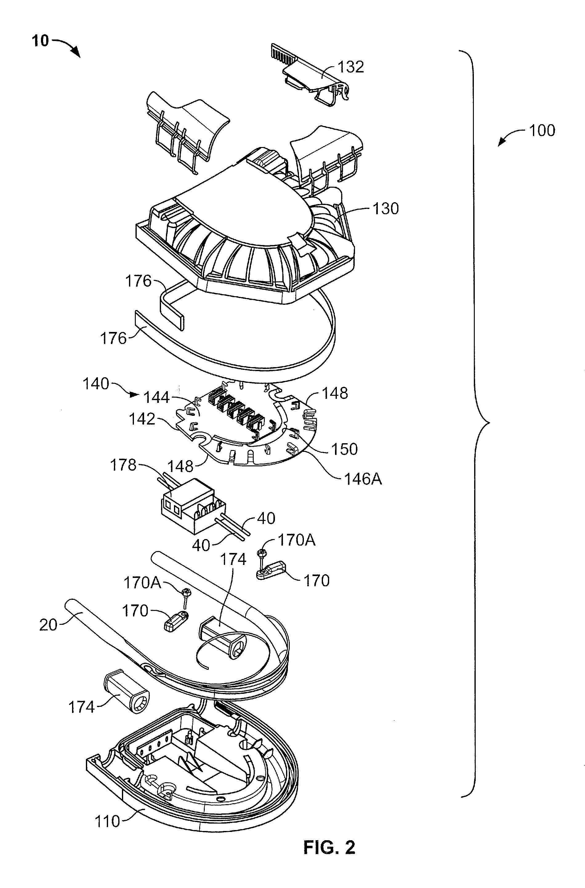
[0033]The present invention now will be described more fully hereinafter with reference to the accompanying drawings, in which illustrative embodiments of the invention are shown. In the drawings, the relative sizes of regions or features may be exaggerated for clarity. This invention may, however, be embodied in many different forms and should not be construed as limited to the embodiments set forth herein; rather, these embodiments are provided so that this disclosure will be thorough and complete, and will fully convey the scope of the invention to those skilled in the art.

[0034]It will be understood that, although the terms first, second, etc. may be used herein to describe various elements, components, regions, layers and / or sections, these elements, components, regions, layers and / or sections should not be limited by these terms. These terms are only used to distinguish one element, component, region, layer or section from another region, layer or section. Thus, a first elemen...


PUM


Abstract

A fiber optic cable connection assembly includes an enclosure housing and a fiber optic cable. The enclosure housing defines a chamber and a fiber handling region disposed in the chamber. The fiber optic cable has a lengthwise cable axis and including a plurality of cable optical fibers, a jacket surrounding the cable optical fibers and a strength member extending through the jacket. The cable includes an arcuately bent cable segment disposed in the chamber. The bent cable segment defines a cable plane and an interior region within the arc of the bent cable segment. At least one of the cable optical fibers extends fully through the enclosure housing uncut. The strength member extends fully through the enclosure housing uncut. The fiber handling region is disposed in the interior region. At least one of the cable optical fibers is removed from the bent cable segment and routed into the fiber handling region where at least a portion of the removed cable optical fiber is stored and / or spliced to another optical fiber.

Description

RELATED APPLICATION(S)[0001]The present application claims the benefit of U.S. Provisional Patent Application No. 61 / 054,628, filed May 20, 2008, the disclosure of which is hereby incorporated herein by reference in its entirety.BACKGROUND OF THE INVENTION[0002]The present invention relates to communication cable termination systems and, more particularly, to optical fiber termination systems and methods for terminating the same.[0003]An extensive infrastructure supporting telecommunication has been developed, traditionally based upon copper wire connections between individual subscribers and telecommunications company network distribution points. More recently, much of the telecommunications network infrastructure is being extended or replaced with an optical fiber based communications network infrastructure. The carrying capacity and communication rate capabilities of such equipment may exceed that provided by conventional copper wired systems.[0004]As such, fiber optic cables are...

Claims


Application Information

Patent Timeline
Patent Type & Authority Applications(United States)
IPC IPC(8): G02B6/00
CPCG02B6/4446G02B6/4475G02B6/4454
Inventor MULLANEY, JULIANCARRICO, WILLIAM ALANTHOMPSON, JUSTIN EVERETTE
Owner COMMSCOPE TECH LLC
Why Eureka
Try Eureka