Cartridge and image forming apparatus

a technology of image forming apparatus and cartridge, which is applied in the field of cartridge and image forming apparatus, can solve the problems of increasing the amount of force necessary to close the door, requiring more time and effort for the user, and increasing the load on the user before the user, so as to achieve the effect of simple structur

Active Publication Date: 2009-11-26
CANON KK
View PDF47 Cites 58 Cited by
  • Summary
  • Abstract
  • Description
  • Claims
  • Application Information

AI Technical Summary

Benefits of technology

[0010]The primary object of the present invention is to provide a cartridge or an image forming apparatus which is simple in structure, and yet, can ensure that the cartridge properly positioned in the main assembly of the image forming apparatus does not move out of the main assembly through the opening with which the main assembly is provided to mount or remove the cartridge.
[0012]According to another aspect of the present invention, there is provided an image forming apparatus for forming an image on a recording material, said apparatus comprising a main assembly including an opening, an urging portion, a positioning portion and a regulating portion; a cartridge dismountably mounted to said main assembly, said cartridge including, a portion to be urged by the urging portion so as to be moved in a crossing direction which crosses an inserting direction in which said cartridge is inserted, after said cartridge is inserted into the main assembly of the apparatus through said opening; a portion to be positioned by contacting to the positioning portion by said cartridge being moved by the urging portion in the crossing direction to position said cartridge relative to the main assembly of the apparatus; and a portion to be regulated by the regulating portion so as to prevent said cartridge from moving toward an outside through said opening in a state that portion to be positioned is in contact to said positioning portion, wherein said portion to be regulated is provided at a rear end of said cartridge and is brought, by movement of said cartridge in the crossing direction by said urging portion, to a regulating position where said portion to be regulated is behind said regulating portion with respect to the inserting direction to prevent said cartridge from moving toward the outside through said opening.

Problems solved by technology

Further, it takes more time and effort for a user to take the pair out of the box and unwrap them after purchasing the image forming apparatus; it increases the amount of load to which the user is subjected before the user can actually use the product.
Further, it makes larger the amount of force necessary to close the door.

Method used


Image

  • Cartridge and image forming apparatus
  • Cartridge and image forming apparatus
  • Cartridge and image forming apparatus

Examples


embodiment 1

General Description of Image Forming Apparatus

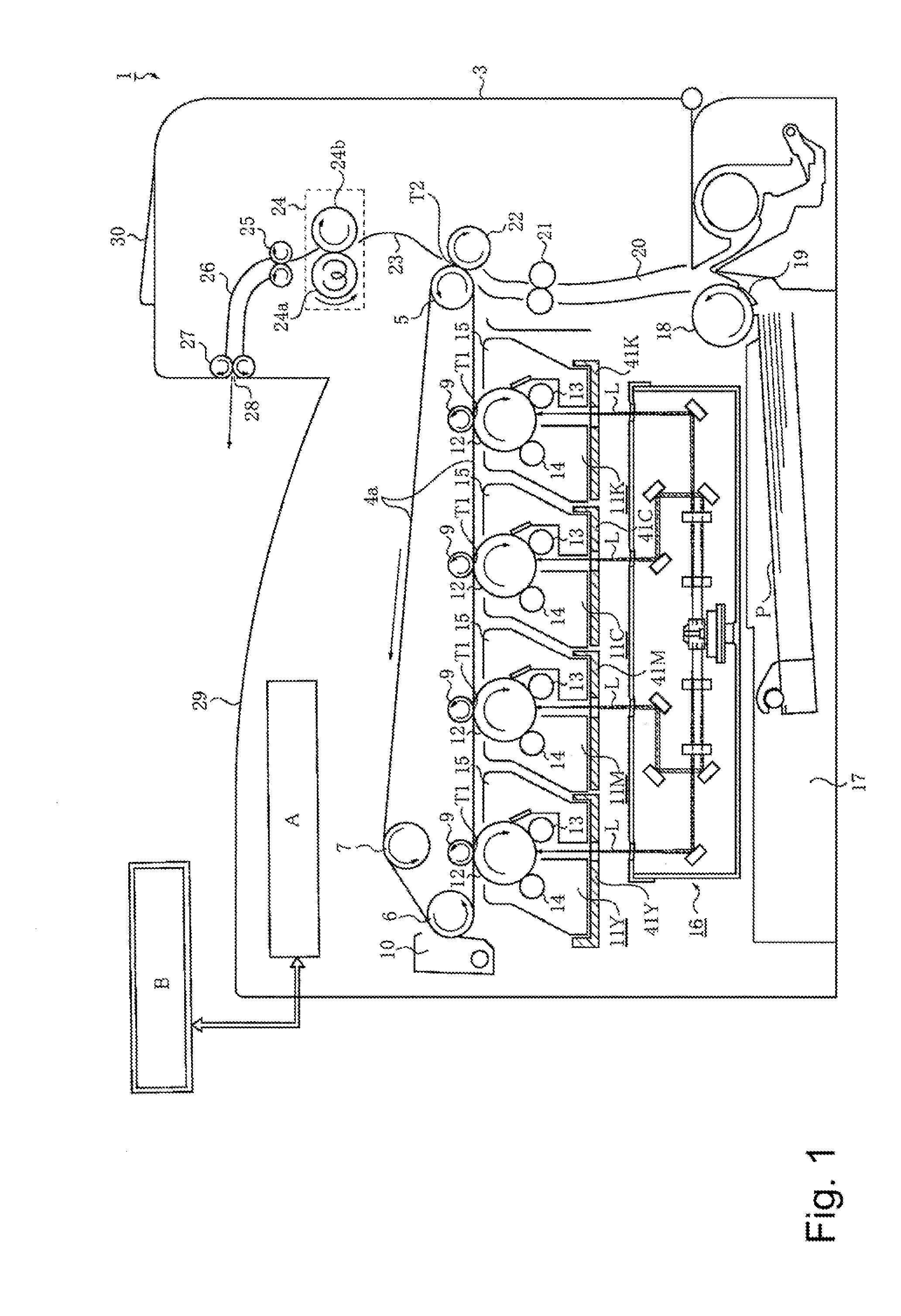
[0029]First, referring to FIG. 1, the image forming apparatus in the first preferred embodiment will be described regarding its overall structure. FIG. 1 is a sectional view of the image forming apparatus in the first embodiment.

[0030]The image forming apparatus1 shown in FIG. 1 employs four process cartridges 11 (11Y, 11M, 11C, and 11K). It is structured so that as the four process cartridges are mounted into its main assembly, they are aligned horizontally in a straight line (they horizontally align in tandem). Further, the main assembly of the image forming apparatus 1, and the four process cartridges 11 (which hereafter will be referred to simply as cartridges), are structured so that the cartridges 11 can be independently mounted into, or removed from, the main assembly, from each other.

[0031]The main assembly 3 of the image forming apparatus is what remains after the removal of all of the process cartridges 11 from the image formin...

embodiment 2

[0090]Next, referring to FIGS. 12 and 13, the second preferred embodiment of the present invention will be described in detail.

[0091]FIG. 12 is a perspective view of the essential portions of the cartridge regulating portion of the image forming apparatus in the second preferred embodiment of the present invention, and is for describing the structures of the essential portions, and in which the tray 41 is in its first position (which allows cartridge to be inserted). FIGS. 13(a)-13(c) are side views of one of the cartridge chambers of the apparatus main assembly 3, and the cartridge 11 which is being mounted into the chamber. They are for describing how the cartridge displacement preventing mechanism operates as the cartridge 11 is mounted in the apparatus main assembly 3.

[0092]This embodiment is different from the first embodiment only in the structure of the cartridge regulating portion of the image forming apparatus. Referring to FIG. 12, unlike the cartridge regulating portion i...

embodiment 3

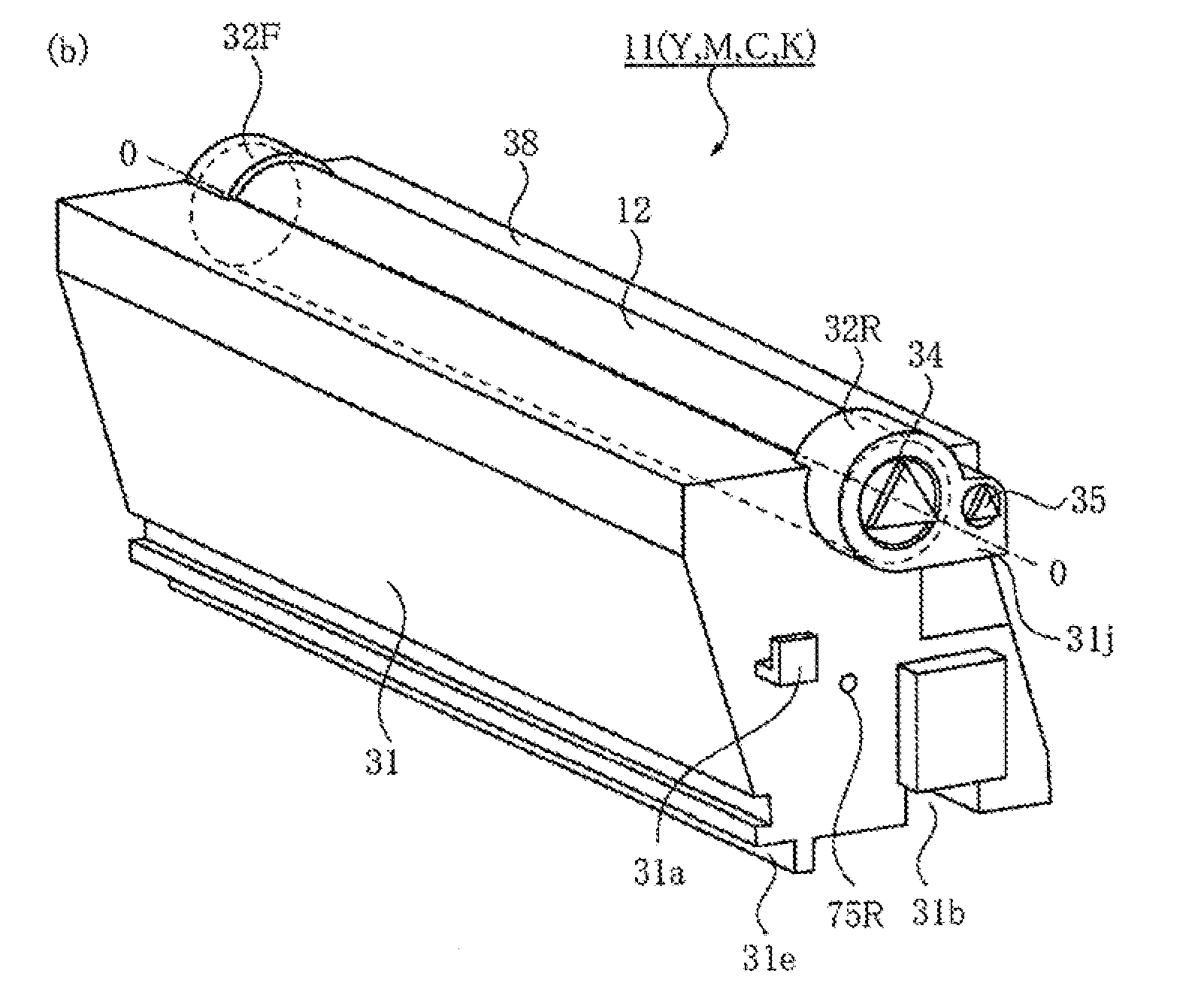
[0097]Next, referring to FIGS. 14 and 15, the third preferred embodiment of the present invention will be described. FIG. 14 is an external perspective view of the cartridge in the third preferred embodiment of the present invention, and depicts the cartridge regulating structure of the cartridge. FIGS. 15(a)-15(c) are side views of the cartridge 11, and one of the cartridge chambers of the main assembly 3 of the image forming apparatus in this embodiment, which are for describing how the cartridge displacement preventing mechanism operates as the cartridge 11 is mounted in the apparatus main assembly 3.

[0098]The third preferred embodiment of the present invention is different from the first one only in the positioning of the cartridge regulating portion of the cartridge 11. Referring to FIG. 14, the cartridge position regulating portions in this embodiment also are made up of the cartridge position regulating portion 38a with which the cartridge is provided, and the cartridge posit...


PUM


Abstract

A cartridge detachably mountable to a main assembly of the image forming apparatus, wherein the main assembly including an opening, an urging portion, a positioning portion and a regulating portion, the cartridge includes a portion to be urged by the urging portion so as to be moved in a crossing direction which crosses an inserting direction in which the cartridge is inserted, after the cartridge is inserted into the main assembly of the apparatus through the opening; a portion to be positioned by contacting to the positioning portion by the cartridge being moved by the urging portion in the crossing direction to position the cartridge relative to the main assembly of the apparatus; and a portion to be regulated by the regulating portion so as to prevent the cartridge from moving toward an outside through the opening in a state that portion to be positioned is in contact to the positioning portion, wherein the portion to be regulated is provided at a rear end of the cartridge and is brought, by movement of the cartridge in the crossing direction by the urging portion, to a regulating position where the portion to be regulated is behind the regulating portion with respect to the inserting direction to prevent the cartridge from moving toward the outside through the opening.

Description

FIELD OF THE INVENTION AND RELATED ART[0001]The present invention relates to a cartridge removably mountable in the main assembly of an image forming apparatus. It also relates to an image forming apparatus which employs a cartridge removably mountable in the main assembly of an image forming apparatus.[0002]One of the examples of an image forming apparatus is an electrophotographic image forming apparatus, which is an apparatus for forming an image on recording medium with the use of an electrophotographic image forming process. These apparatuses include an electrophotographic copying machine, an electrophotographic printer (LED printer, laser beam printer, etc.), an electrophotographic facsimile apparatus, and an electrophotographic word processor, for example.[0003]A recording medium is a medium on which an image is formed. As for examples of a recording medium, there are recording sheet, OHP sheet, etc.[0004]A cartridge means a container, which is removably mountable in the main...

Claims


Application Information

Patent Timeline
Patent Type & Authority Applications(United States)
IPC IPC(8): G03G21/18
CPCG03G21/1842G03G21/185G03G2221/1884G03G2221/169G03G2221/1654
Inventor KAWAI, TACHIOHORIKAWA, TADASHITAKARADA, HIROSHINAKANISHI, TAKASHI
Owner CANON KK
Why Eureka
Try Eureka