Inductive heating of workpiece using coiled assemblies, system and method

a technology of inductive heating and workpiece, applied in the direction of induction current source, electric/magnetic/electromagnetic heating, disinfection, etc., can solve the problems of limited heating of small workpieces or localized areas, increasing the potential for injury during operation, and usually limited to large workpieces

Active Publication Date: 2009-11-26
TEAM INDAL SERVICES
View PDF4 Cites 15 Cited by
  • Summary
  • Abstract
  • Description
  • Claims
  • Application Information

AI Technical Summary

Problems solved by technology

A disadvantage of this method is that it is usually limited to heating smaller workpieces or localized areas on larger workpieces due to the large power requirement and lengthy time to wrap wire and heating elements around the workpiece.
Another disadvantage is the fact that the conductor itself becomes very hot, thereby increasing the potential for injury during operation.
A disadvantage of this method is that it is usually limited to large workpieces that do not need finite temperature control and heat placement.
It is presently thought that the induction technique heats the workpiece by the result of hysteresis and eddy current losses in the workpiece.
As the workpiece is increased in size and / or irregularity in its shape, the design and manufacture of an effective heating coil to produce the required temperature and / or heating profile in the container becomes problematic.
Although this method of “flexible coil” induction heating has been used in industry, it suffers from numerous and significant disadvantages.
One primary disadvantage is that installation of the flexible coil around the container is not only time and labor intensive but is prone to inconsistencies.
It is a long and laborious process to individually wrap and position the flexible coil around the container, and the placement and effectiveness of the flexible coil often varies significantly between each container as a result of inconsistencies and installation error.
Another common problem is that there is no good way to heat the ends of the container with the use of the traditional flexible coil method.
In the case of a cylindrical container, the flexible coil can (with enough time and labor) be wrapped around the shell face of the container, but it is very difficult to wrap the end faces of the cylindrical container with flexible coils, and much more difficult to wrap the end face with any type of precision and consistency.
The unwrapped end faces further provides for inconsistent and ineffective heating results of the container, and as a result, the container cannot be efficiently and / or effectively decontaminated.

Method used


Image

  • Inductive heating of workpiece using coiled assemblies, system and method
  • Inductive heating of workpiece using coiled assemblies, system and method
  • Inductive heating of workpiece using coiled assemblies, system and method

Examples


Embodiment Construction

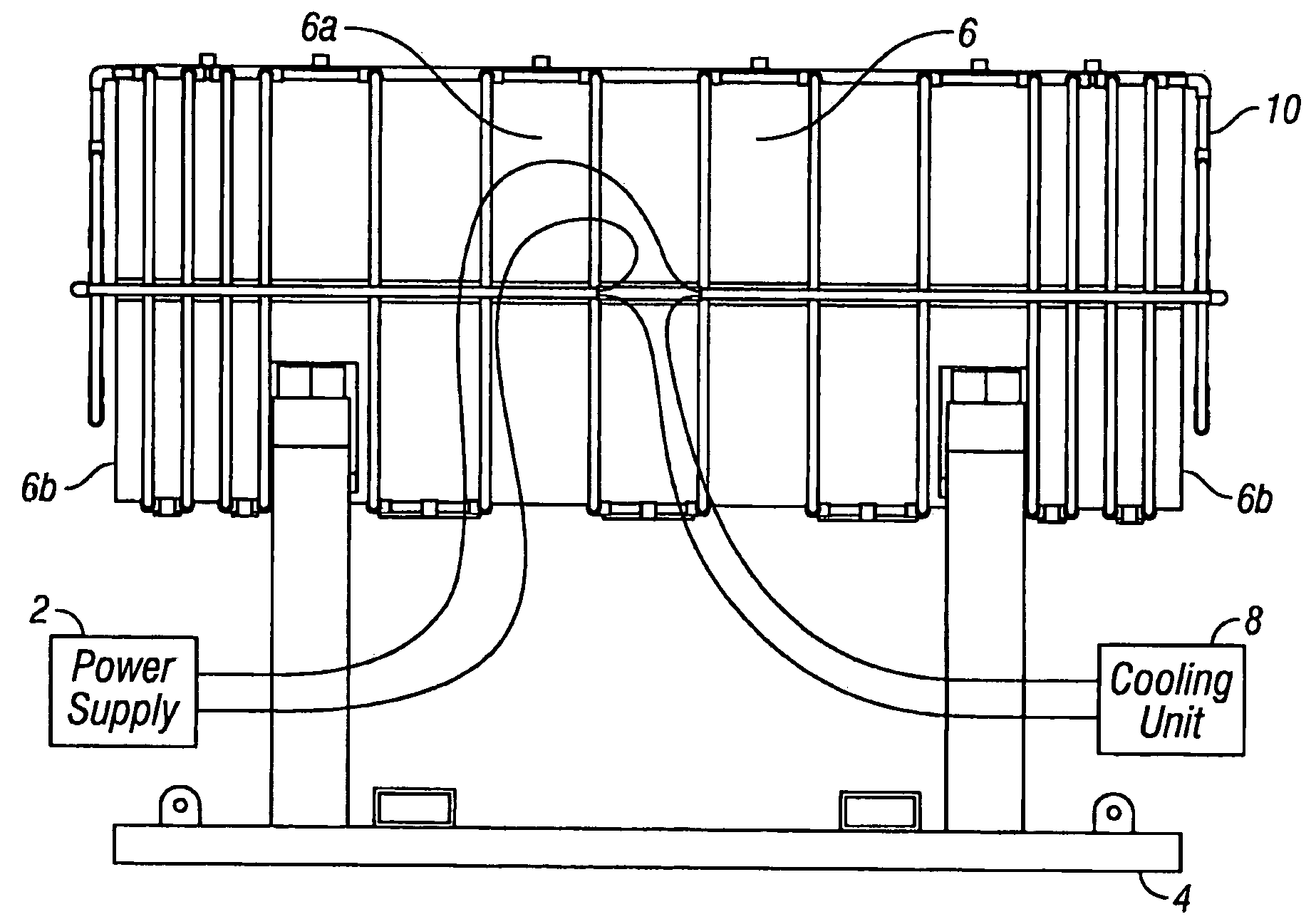
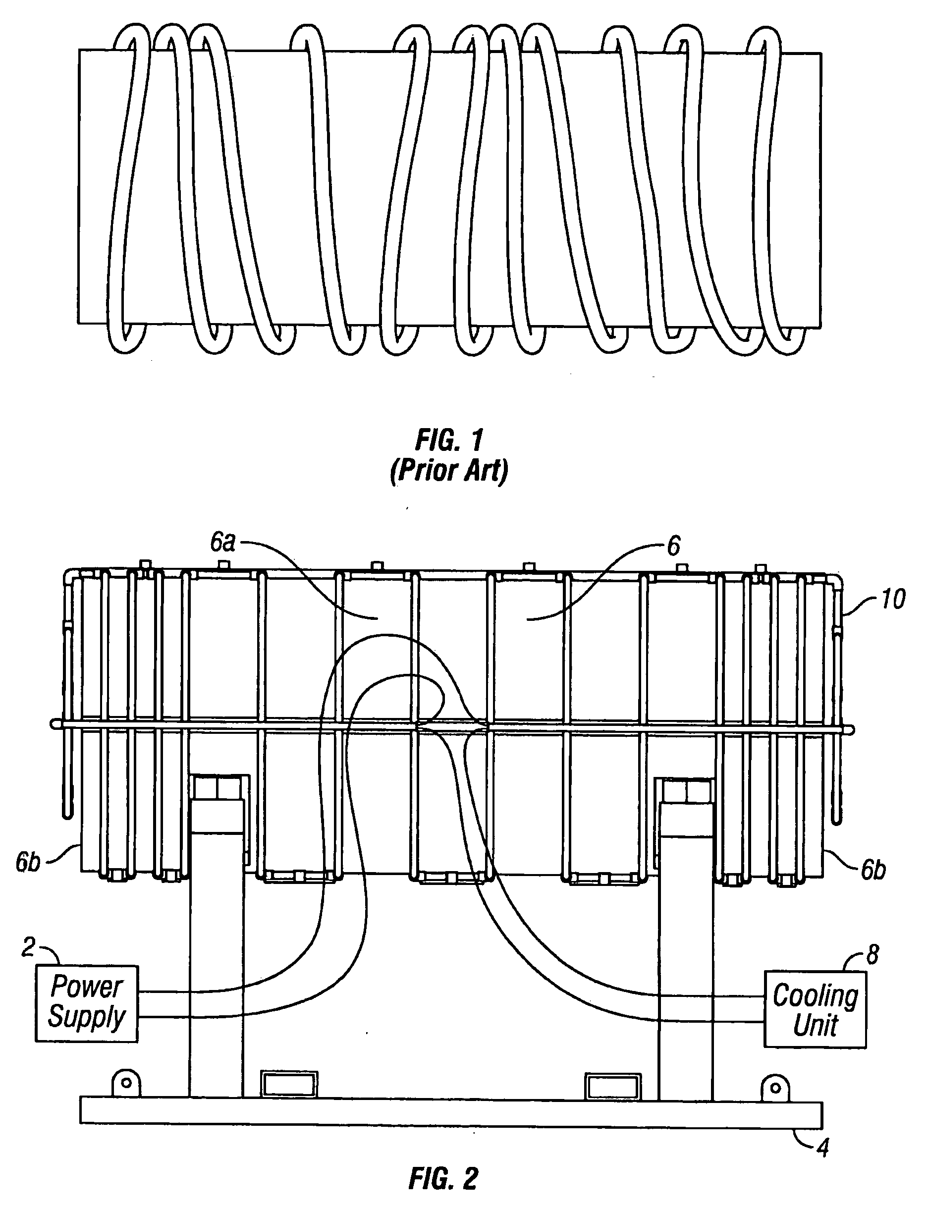
[0017]Referring to FIG. 2, a preferred embodiment of the present invention is illustrated. FIG. 2 shows a power supply 2, a support cradle 4, a container 6, a cooling unit 8, and a heating coil 10. The power supply 2 supplies a high frequency alternating current to the heating coil 10, and can be any commercially available induction heating unit (for example, a portable 35-kW induction heating unit with a 60-amp, 480-VAC, 3 phase power supply). The power supply 2 induces a magnetic field around the container 6, and the output of the power supply 2 determines the speed and degree at which the container 6 can be heated. It is well known in the art that the specifications of the power supply 2 depend upon the specifications of the container 6 and the specific heating application (such as surface hardening, melting, brazing, soldering, heating to fit, and decontamination). The support cradle 4 is made to support the container 6 before, during, and / or after heating the container 6. The s...


PUM

PropertyMeasurementUnit
temperatureaaaaaaaaaa
lengthaaaaaaaaaa
outer diameteraaaaaaaaaa

Abstract

A system for inductively heating a workpiece including a heating coil that surrounds the sides and ends of the workpiece, wherein the heating coil comprises a first coil assembly that encloses a first portion of the workpiece and a second coil assembly that encloses a second portion of the workpiece. A power supply is operatively connected to the first coil assembly and the second coil assembly.

Description

BACKGROUND OF THE INVENTION[0001]The present invention relates generally to a method and system for inductively heating a workpiece, and more specifically to a method and system for inductively heating a workpiece by a plurality of coiled tubing assemblies.[0002]There are many different approaches in heating a “workpiece” (the material to be heated), and the selected approach depends on many considerations, such as the purpose for the heating, size and specifications of the workpiece, power requirements, and time limitations for the heating process. A few commonly known methods for heating a workpiece include the use of electrical resistance, combustion, and induction. The electrical resistance method generally involves the creation of heat by the flow of electric current through a conductor or element of high resistance. A disadvantage of this method is that it is usually limited to heating smaller workpieces or localized areas on larger workpieces due to the large power requiremen...

Claims


Application Information

Patent Timeline
Patent Type & Authority Applications(United States)
IPC IPC(8): A61L2/04H05B6/04
CPCH05B6/40A61L2/04
Inventor WALLACE, TREVORHAND, KURT D.KEARNS, JOHN P.
Owner TEAM INDAL SERVICES
Why Eureka
Try Eureka