Mechanical embolectomy device and method

a technology of embolism and occlusion, applied in the field of mechanical embolism device and method, can solve the problems of limited utility for patients with large clots, significant time constraints of tpa therapy, and cerebral blood flow disruption

Inactive Publication Date: 2009-11-26
RAZACK NASSER
View PDF48 Cites 198 Cited by
  • Summary
  • Abstract
  • Description
  • Claims
  • Application Information

AI Technical Summary

Problems solved by technology

The goal of therapy is to restore perfusion to the ischemic but potentially salvageable brain tissue rather than to the irreversibly damaged brain tissue, since re-establishing blood flow to such damaged tissue can cause complications such as hemorrhage.
Most patients with acute ischemic stroke have thromboembolic material occluding large cerebral vessels and hence disruption of cerebral blood flow.
This treatment is suitable for

Method used


Image

  • Mechanical embolectomy device and method
  • Mechanical embolectomy device and method
  • Mechanical embolectomy device and method

Examples


Embodiment Construction

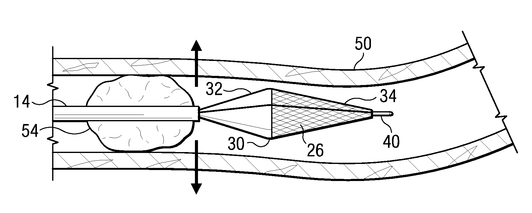
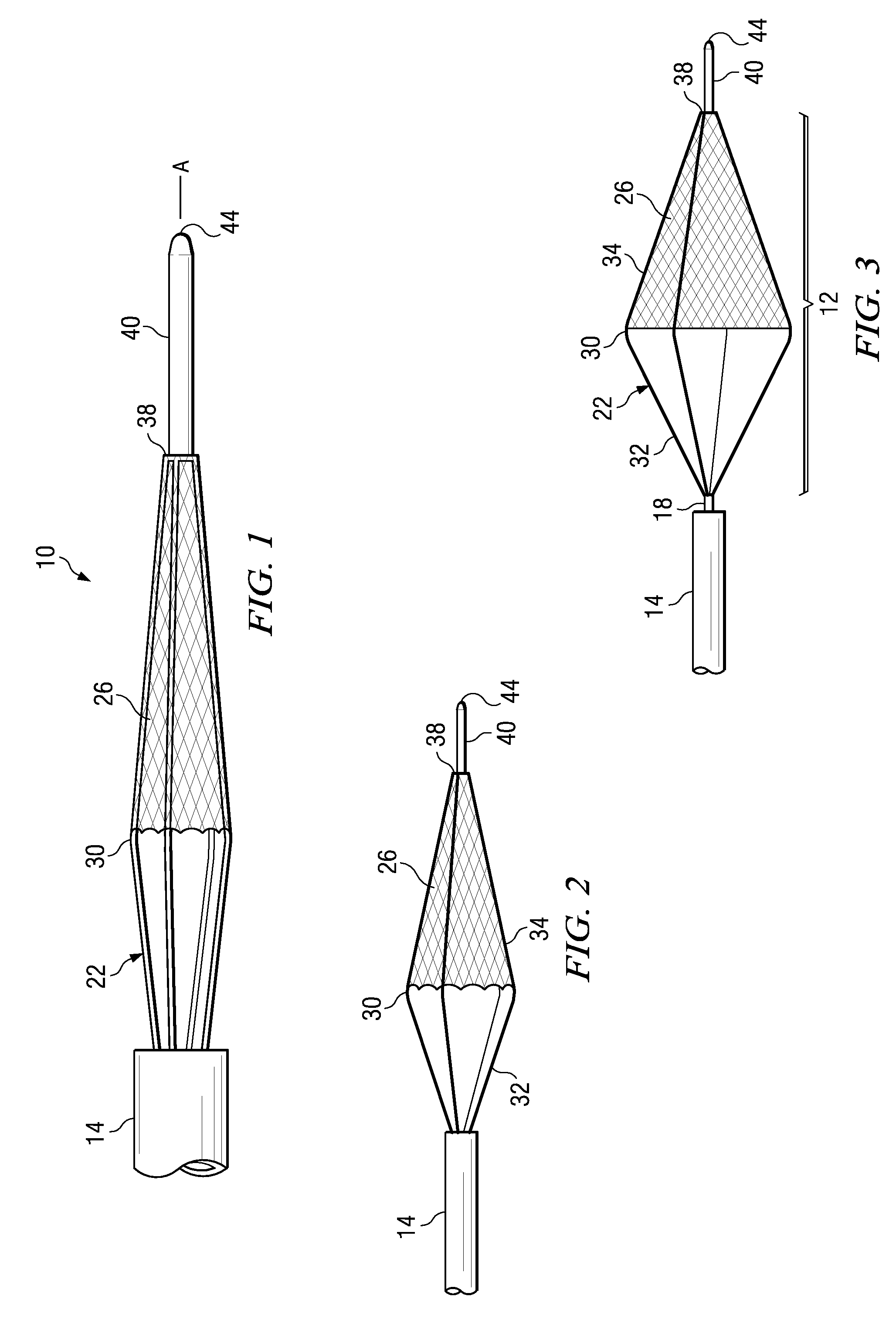
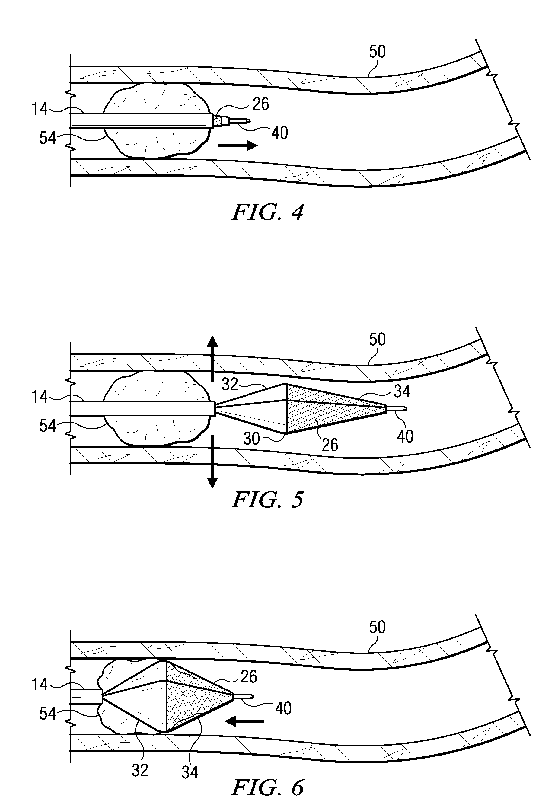
[0028]There is shown in FIGS. 1-3 an embolectomy device 10 according to the invention. The embolectomy device 10 comprises a microcatheter 14 having an elongated shaft such as guide wire 18 extending through an opening in the microcatheter 14. The elongated shaft 18 can have proximal and distal end portions. A retrieval portion 12 can be provided at or near the distal end portion of the elongated shaft 18. The retrieval portion may be formed from or attached to the elongated shaft 18. The retrieval portion 12 can have a plurality of legs such as spring arms 22 that are connected to the guide wire 18. The spring arms 22 are disposed about a long axis A of the guide wire 18. The spring arms 22 are biased or otherwise moveable to extend partially outwardly (FIG. 2) when not constrained entirely by the microcatheter 14. When unconstrained by the microcatheter 14 (FIG. 3) the spring arms 22 can extend laterally outward a maximum distance. Movement of the spring arms 22 relative to the mi...


PUM


Abstract

An embolectomy device includes a catheter and an elongated shaft positioned in and moveable within the catheter. The shaft has proximal and distal end portions, and a retrieval portion between the proximal and distal end portions. The retrieval portion has a plurality of legs having proximal and distal end portions. Portions of the legs are movable laterally outward from a long axis of the elongated shaft when the retrieval portion is at least partially moved out of the catheter. A retrieval net can be fixed to portions of the legs for engaging a clot or other occlusion within a body canal. An expander can be provided for moving portions of an occlusion toward canal walls to open a lumen. A method for removing clots and other occlusions from body canals is also disclosed.

Description

BACKGROUND OF THE INVENTION[0001]There are currently in excess of 700,000 new or recurrent strokes every year in the United States. It is the third leading cause of death in the United States after coronary artery disease and cancer. Approximately 40% (>250,000) of strokes are due to large vessel occlusion, potentially requiring a device for treatment.[0002]Treatment must begin with an evaluation of the patient. Diagnostic neuroimaging is used to obtain noninvasive real-time information about the patient. The goal of therapy is to restore perfusion to the ischemic but potentially salvageable brain tissue rather than to the irreversibly damaged brain tissue, since re-establishing blood flow to such damaged tissue can cause complications such as hemorrhage. Determining the cause and location of the blockage is critical to planning the treatment approach. The most common cause of ischemic stroke is acute embolic occlusion. Most patients with acute ischemic stroke have thromboembolic...

Claims


Application Information

Patent Timeline
IPC IPC(8): A61M29/00
CPCA61B17/22004A61B17/221A61B17/320758A61B2017/22034A61B2017/22094A61M2025/0096A61B2017/2215A61M29/02A61M2025/0004A61M2025/0042A61B2017/2212
Inventor RAZACK, NASSER
Owner RAZACK NASSER
Why Eureka
Try Eureka