Method for detecting malfunction of valve on the downstream side of throttle mechanism of pressure type flow control apparatus

Active Publication Date: 2009-11-26
FUJIKIN INC
View PDF7 Cites 20 Cited by
  • Summary
  • Abstract
  • Description
  • Claims
  • Application Information

AI Technical Summary

Benefits of technology

[0028]The present invention is so constituted that changes are made by means that a flow rate setting value Qe of a pressure type flow control apparatus is switched to “ON” or “OFF” either concurrently with opening or closing operations of a valve on the downstream side of a throttle mechanism of a pressure type flow control apparatus, or with a delay of a given time Δt after opening/closing operations of the valve on the downstream side having been made, thus determining whether the valve on the downstream side of the throttle mechanism is functioning normally or not by observing the changes of a flow rate output signal Qo between opening or closing operations of the valve on the downstream side of the throttle mechanism and also between “ON” or “OFF” of the flow rate setting value Qe. As a

Problems solved by technology

Furthermore, a pressure type flow control apparatus rivals, or exceeds, a thermal type flow control apparatus both in accuracy and responsiveness.
When opening/closing operations of the valve V3 on t

Method used


Image

  • Method for detecting malfunction of valve on the downstream side of throttle mechanism of pressure type flow control apparatus
  • Method for detecting malfunction of valve on the downstream side of throttle mechanism of pressure type flow control apparatus
  • Method for detecting malfunction of valve on the downstream side of throttle mechanism of pressure type flow control apparatus

Examples


embodiment 1

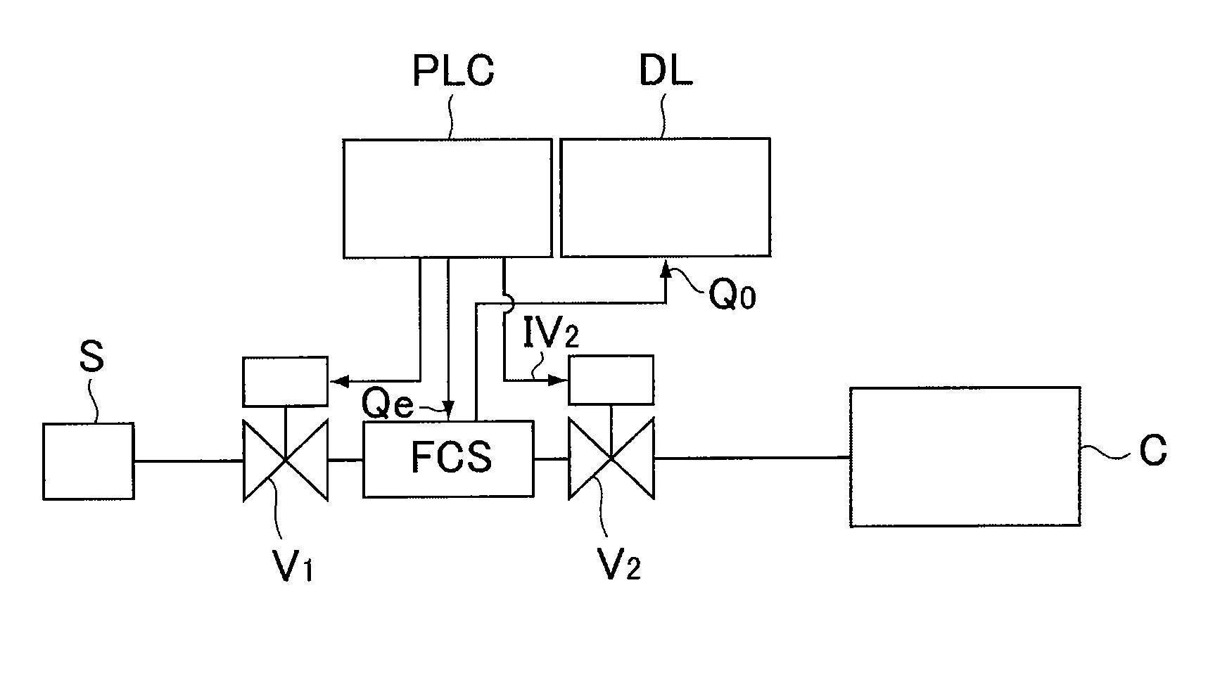
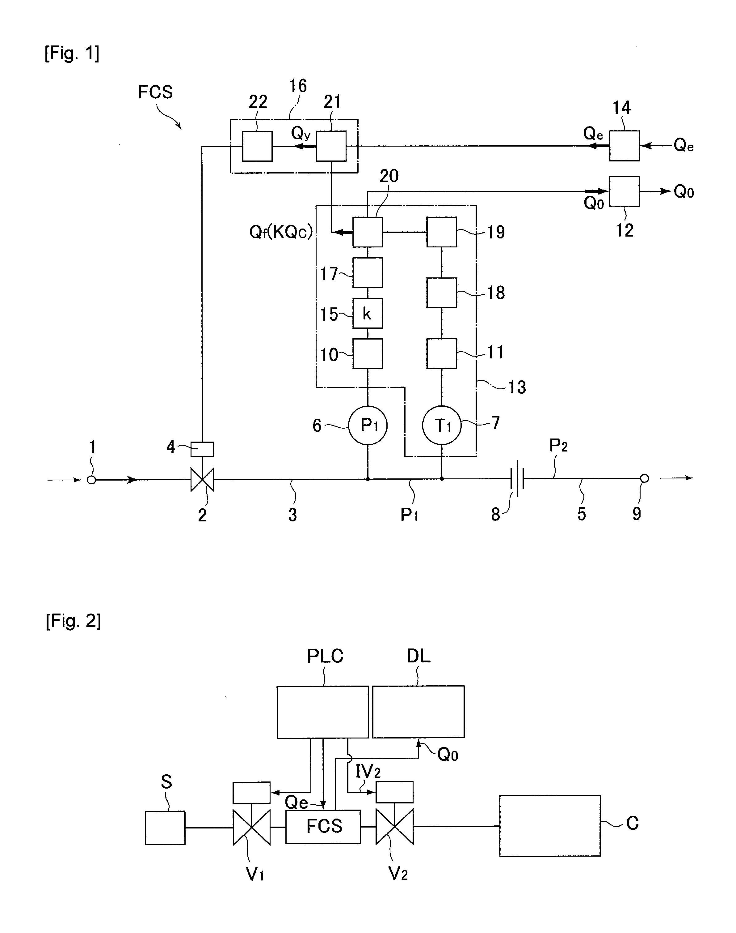
[0093]FIG. 2 is an explanatory drawing of a test unit used for executing a method for detecting the malfunction of a valve on the downstream side of a throttle mechanism in accordance with Embodiment 1 of the present invention. Namely, as shown in FIG. 2, the test unit is so constituted that a gas supply valve V1 and a valve V2 on the downstream side of the throttle mechanism are connected to the upstream side and downstream side of a pressure type flow control apparatus FCS respectively, thereon a programmable controller PLC and a data logger DL are set, and following the prescribed program from the programmable controller PLC, a flow rate setting signal Qe is supplied to valves V1, V2 and a flow rate setting circuit 14 of a pressure type flow control apparatus FCS, and a valve releasing signal IV2 to a valve V2, a flow rate setting signal Qe to the FCS and a flow rate output signal Qo from the FCS are recorded on the data logger respectively. With FIG. 2, S designates a gas source...

embodiment 2

[0097]Embodiment 2 is made so that an operational malfunction of a valve V2 on the downstream side of a throttle mechanism is detected at the time of the completion of a process treatment. FIG. 4 is an explanatory drawing of a test system used with Embodiment 2. In FIG. 4, EV designates an operational electro-magnetic valve, V1 designates a valve on the FCS upstream side, Pe designates a vacuum pump, Pb designates a Baratron vacuum pump, VR designates a flow rate valve, N2 designates an operational gas, and PG designates a process gas.

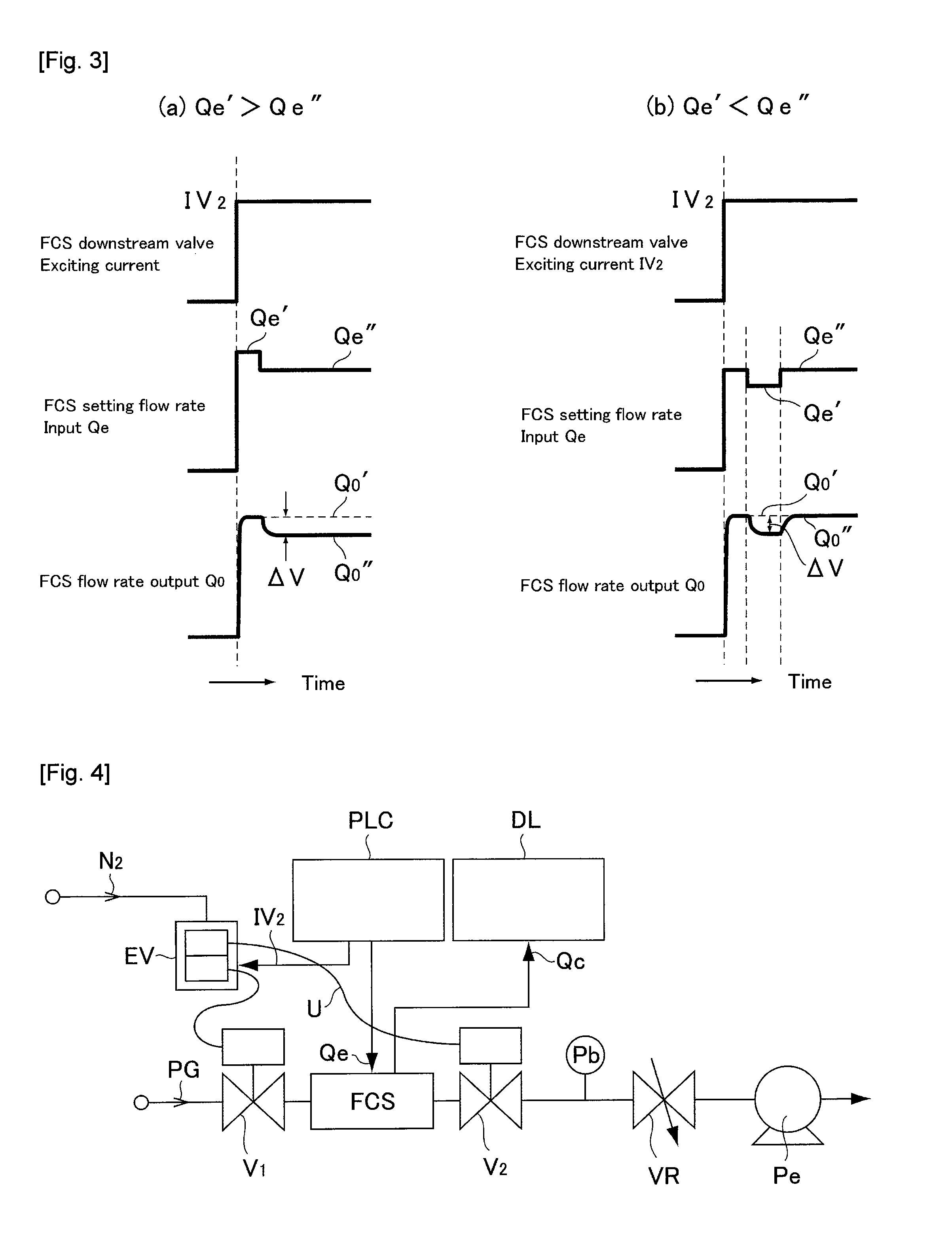
[0098]The detection of the operational malfunction of the valve V2 on the downstream side of the throttle mechanism has been performed in a manner such that changes of a FCS flow rate output signal Qo are monitored after a flow rate setting signal Qe to the FCS is set to zero (the FCS shutdown) at the time when a treatment process is terminated, for two distinct cases. In one case, as shown in FIG. 5(a), the shutdown of a flow rate setting signal Qe of...

embodiment 3

[0103]With Embodiment 3, the malfunction of a valve V2 on the downstream side of a throttle mechanism (releasing not functioning) is detected by monitoring a FCS flow rate output signal at the time of a startup of a pressure type flow control apparatus FCS. This is mainly used to detect any operational malfunction of valve V2 on the downstream side of the throttle mechanism during the preparatory stage of starting up a process system.

[0104]A test device used with Embodiment 3 is same as that shown in FIG. 4. Specifically, with Embodiment 3, the malfunction of a releasing operation of a valve V2 on the downstream side of the throttle mechanism is determined by monitoring the drop quantity of a FCS flow rate output signal Qo which occurs within a time Δt (a delay time Δt=0.2 sec) from a valve V1 on the primary side of the pressure type flow control apparatus FCS, and valve V2 on the downstream side of the throttle mechanism is released until a flow rate setting signal Qe being inputte...


PUM


Abstract

With a pressure type flow control apparatus, a valve on the downstream side of a throttle mechanism is released and a flow rate setting value Qe inputted to the pressure type flow control apparatus is changed to detect the magnitude ΔV of change of a flow rate output signal Qo from the pressure type flow control apparatus while the flow rate setting value Qe is changed, so that normal functioning of the releasing operations of the valve on the downstream side of the throttle mechanism is confirmed when the magnitude ΔV of change of the flow rate output signal Qo is above the predetermined value. If the releasing operations are malfunctioning, the magnitude ΔV of changes is found to be below the predetermined value.

Description

[0001]This is a National Phase Application in the United States of Application No. PCT / JP2007 / 000630 filed Jun. 13, 2007, which claims priority on Japanese Patent Application No. 2006-183061, filed Jul. 3, 2006. The entire disclosures of the above patent applications are hereby incorporated by reference.FIELD OF THE INVENTION[0002]The present invention relates to a method for detecting the malfunction of a valve installed on the downstream side of a throttle mechanism in a pressure type flow control apparatus by monitoring a flow output signal, and it is mainly directed at the use for fluid supply facilities with a pressure type flow control apparatus to be used with semiconductor manufacturing, food processing, chemical products-related facilities, and the like.BACKGROUND OF THE INVENTION[0003]In recent years, pressure type flow control apparatus have been increasingly used in gas supply facilities in semiconductor manufacturing, chemical products-related facilities, and the like, ...

Claims


Application Information

Patent Timeline
IPC IPC(8): G05D7/06
CPCG01F1/36G05D7/0635G01F15/022G01F15/005G05D7/06G01F1/00
Inventor NAGASE, MASAAKIDOHI, RYOUSUKEIKEDA, NOBUKAZUNISHINO, KOUJIHIRATA, KAORUSUGITA, KATSUYUKIMATSUMOTO, ATSUSHI
Owner FUJIKIN INC
Why Eureka
Try Eureka