Hydraulic power generation system driven by compression air produced by fluid

a technology of compression air and hydraulic power generation system, which is applied in the direction of electric generator control, greenhouse gas reduction, fluid coupling, etc., can solve the problems of wind power generators that cannot collect smaller wind power to obtain larger ones, and can not guide smaller hydraulic power, so as to achieve the effect of potential energy and potential energy

Inactive Publication Date: 2009-12-03
CHEN TIEN CHUAN
View PDF5 Cites 17 Cited by
  • Summary
  • Abstract
  • Description
  • Claims
  • Application Information

AI Technical Summary

Problems solved by technology

However, such a wind power generator is incapable of collecting smaller wind power to obtain a larger one for use.
Conventional hydraulic power generator and tidal power generator have a similar disadvantage as being incapable of guiding smaller hydraulic power to the land and collectively storing to obtain a large power for use.

Method used


Image

  • Hydraulic power generation system driven by compression air produced by fluid
  • Hydraulic power generation system driven by compression air produced by fluid
  • Hydraulic power generation system driven by compression air produced by fluid

Examples


Embodiment Construction

[0019]The accompanying drawings are included to provide a further understanding of the invention, and are incorporated in and constitute a part of this specification. The drawings illustrate embodiments of the invention and, together with the description, serve to explain the principles of the invention.

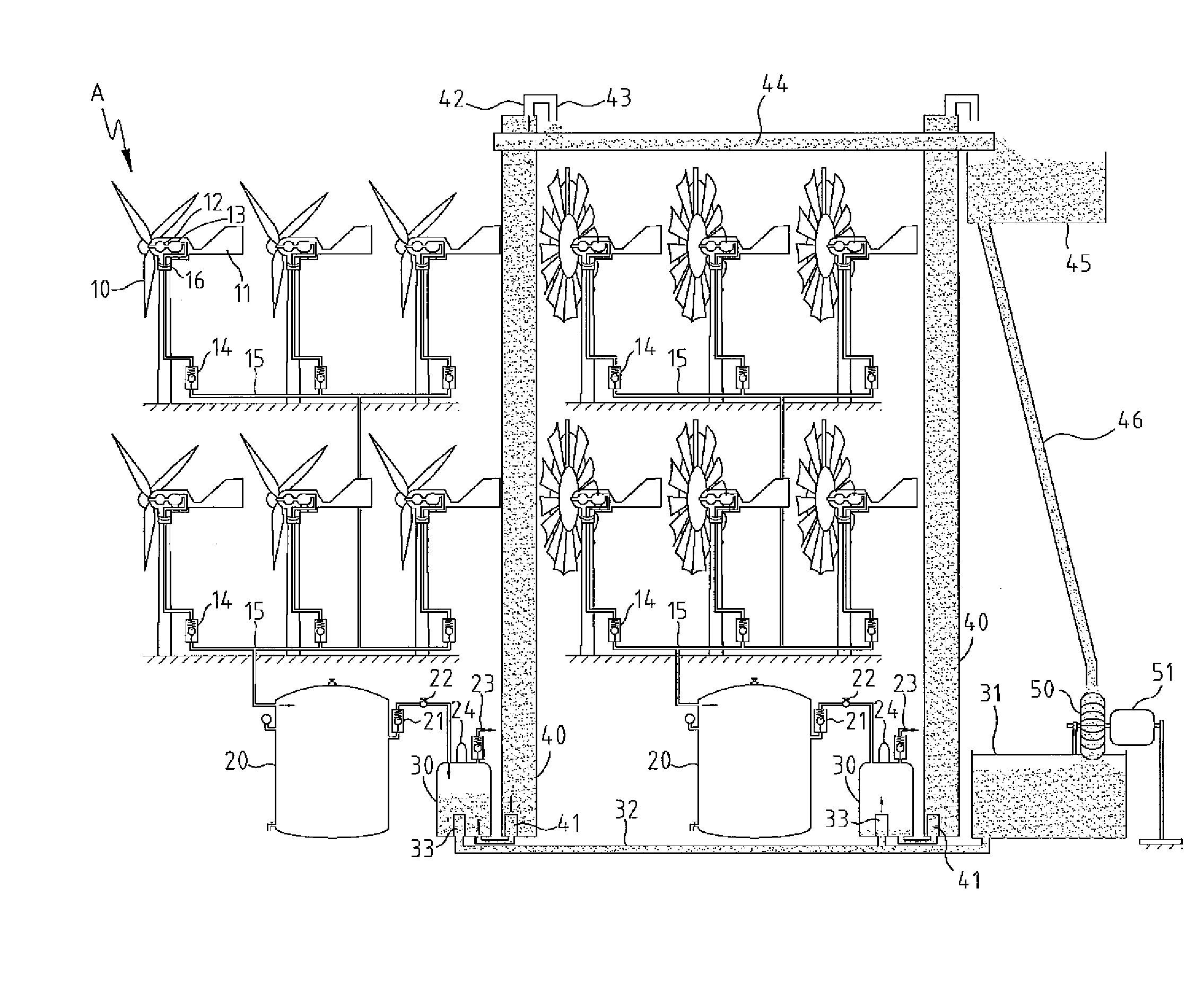
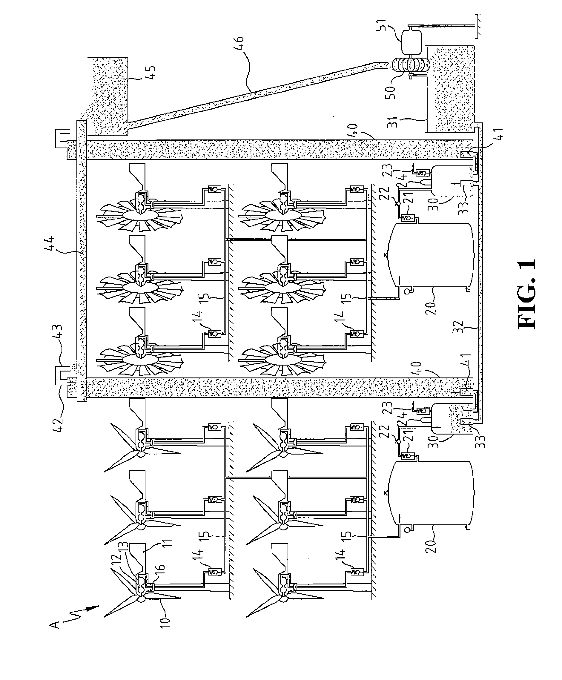
[0020]FIG. 1 is a schematic diagram illustrating a hydraulic power generation system producing compression air by wind power then storing the compression air, for further driving a hydraulic power generator to generate power according to an embodiment of the present invention. Referring to FIG. 1, the hydraulic power generation system includes more than one group of windmills A, at least one group of air compression tanks 20, at least one hermetic tank 30, at least one hermetic water tower 40, and at least one set of power generator 51.

[0021]Each windmill A is equipped with wings 10. The wings 10 are configured for enduring wind power, and can be configured with any forms, e.g., the ...


PUM


Abstract

A hydraulic power generation system driven by compression air produced by fluid is provided. The present invention is featured in that it employs more than one group of windmills which can be driven by wind power, or utilizes hydraulic power, such as a river flow, tides at estuaries or bays to drive more than one group of hydraulic turbines. The rotation power of the windmills or the hydraulic turbines then drives a transmission and subsequently drives an air compressor to produce compression air. The compression air is compressed with a specific pressure and collectively stored in an air compression tank. The compression air stored in the air compression tank is guided to a water filled hermetic tank. The hermetic tank is connected with a hermetic water tower having a certain height, in which the hermetic tanks and the hermetic water tower are connected with a communicating pipe by which a pressure can be conducted. According to the Pascal's principle, when suffering the pressure of the compression air, the water stored in the hermetic tank is transmitted to the hermetic water tower up to a certain height thus obtaining a potential energy. The water is collectively stored at the certain height to obtain a large amount. Such a large amount of water can be downwardly guided to drive a hydraulic turbine which is connected to a power generator for generating power. After releasing the potential energy, the water can be conducted back to the hermetic tank via another communicating pipe for recycle use.

Description

BACKGROUND OF THE INVENTION[0001]1. Field of the Invention[0002]The present invention relates generally to a power generation system, and more particularly, to a power generation system adapted for generating power by natural power.[0003]2. The Prior Arts[0004]Current conventional wind power generation is typically applied by disposing a plurality of windmills in a clear wild site. Wind drives the windmill to rotate, and the rotation power is then transmitted to a generator to generating power. However, such a wind power generator is incapable of collecting smaller wind power to obtain a larger one for use.[0005]Conventional hydraulic power generator and tidal power generator have a similar disadvantage as being incapable of guiding smaller hydraulic power to the land and collectively storing to obtain a large power for use.[0006]As such, with respect to the loss of the foregoing smaller power, it is desired by the power scientific and technological enterprises to collectively stori...

Claims


Application Information

Patent Timeline
Patent Type & Authority Applications(United States)
IPC IPC(8): F03B13/10F04B17/02F01B23/10
CPCF03B13/06Y02E60/17F03B13/264F03B13/266F03B17/061F03D9/008F03D9/025F03D9/028F05B2240/133F05B2240/2211F05B2240/96Y02E10/28Y02E10/72Y02E60/15F03B13/08F03D9/14F03D9/17Y02E10/30Y02E60/16Y02E70/30Y02P80/10Y02P90/50Y02E10/20
Inventor CHEN, TIEN-CHUAN
Owner CHEN TIEN CHUAN
Why Eureka
Try Eureka