
Driving device for a parking brake system

a technology of driving device and parking brake, which is applied in the direction of brake system, friction lining, gearing, etc., can solve the problems of prolonging the life of the brake cable, and achieve the effect of increasing the life span and mechanical efficiency of the electronic parking brake system

Active Publication Date: 2009-12-03
AUTOMOTIVE RES & TESTING CENT
View PDF3 Cites 4 Cited by
  • Summary
  • Abstract
  • Description
  • Claims
  • Application Information

AI Technical Summary

Benefits of technology

[0011]The primary objective of the present invention is to provide a driving device for a parking brake system that uses a single brake cable, which is especially suitable for an electronic parking brake system and can increase a life span and a mechanical efficiency of the electronic parking brake system.
[0012]A driving device for a parking brake system in accordance with the present invention comprises a casing shift member, a brake cable mounted through the casing shift member and a driving member. The casing shift member comprises at least one cable casing. The brake cable mounted through the cable casing. The driving member comprises a driving unit connected to and driving the casing shift member to perform a longitudinal motion. Thus the cable casing applies a force on the brake cable so as to perform the brake work. Because the brake cable is tightened with the force provided by the cable casing, the brake cable is only bent slightly. Thus the curvature of the brake cable in accordance with the present invention is smaller than the driving device of the prior art. That prevents the brake cable from being damaged easily and prolongs a life span of the brake cable. Moreover, a mechanical efficiency of the driving device is improved because the brake cable is tightened with the force provided by the cable casing so as to reduce the curvature of the brake cable.

Problems solved by technology

That prevents the brake cable from being damaged easily and prolongs a life span of the brake cable.

Method used


Image

  • Driving device for a parking brake system
  • Driving device for a parking brake system
  • Driving device for a parking brake system

Examples


Embodiment Construction

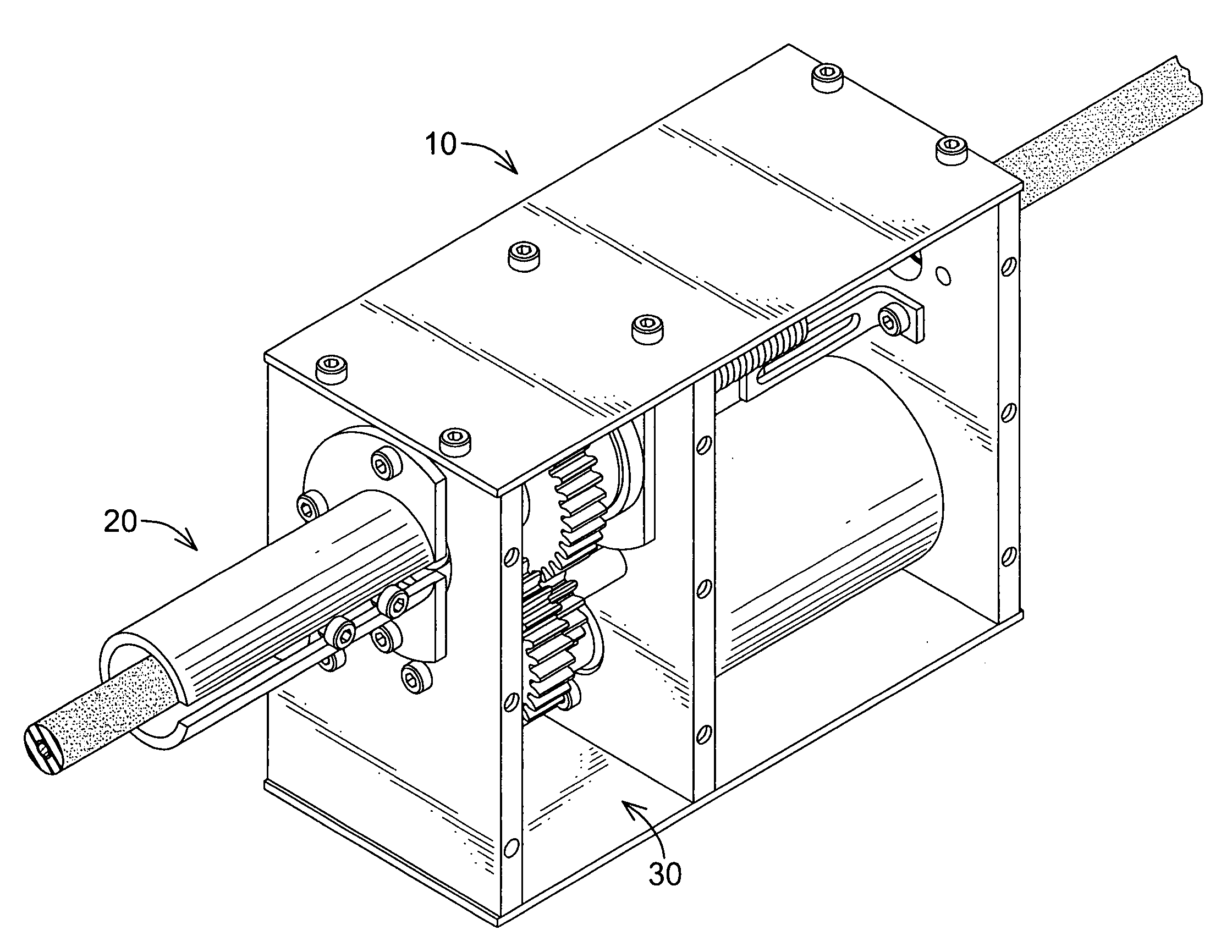
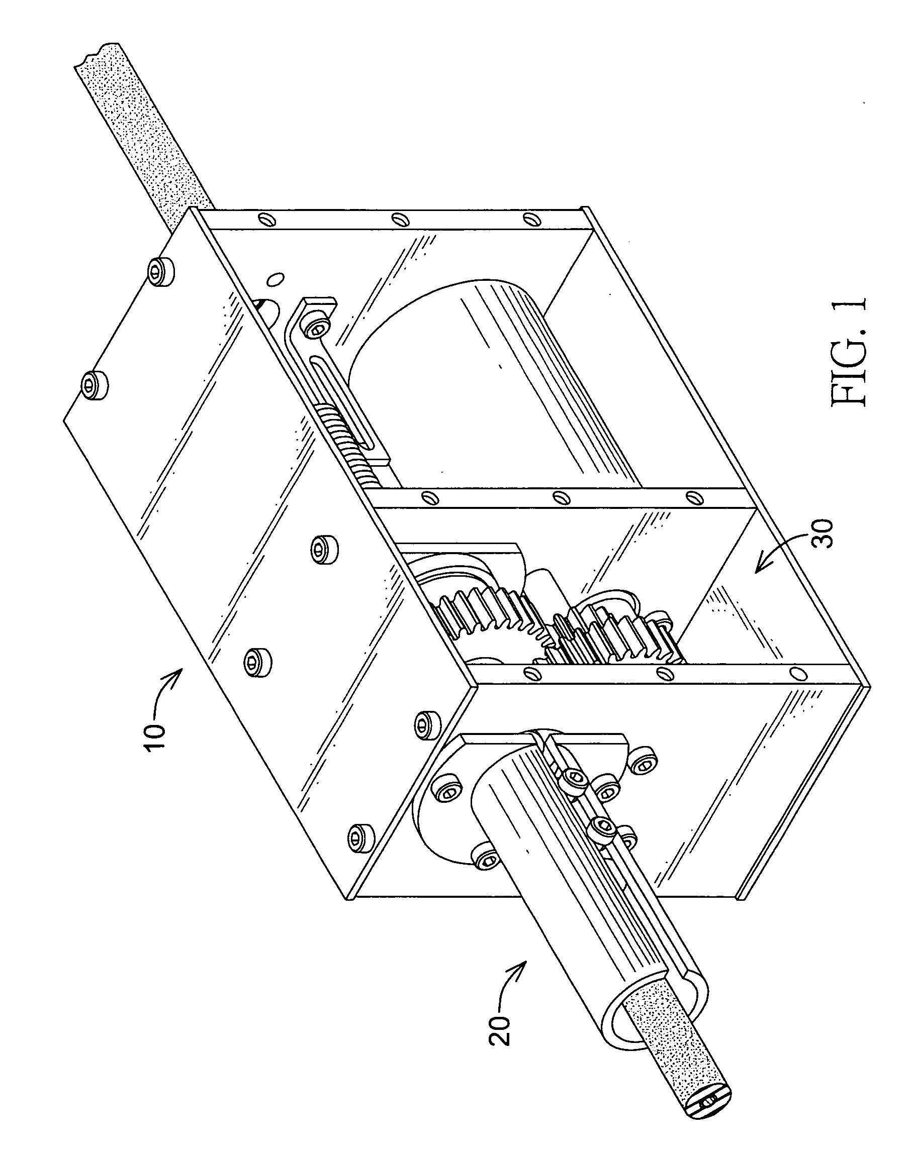
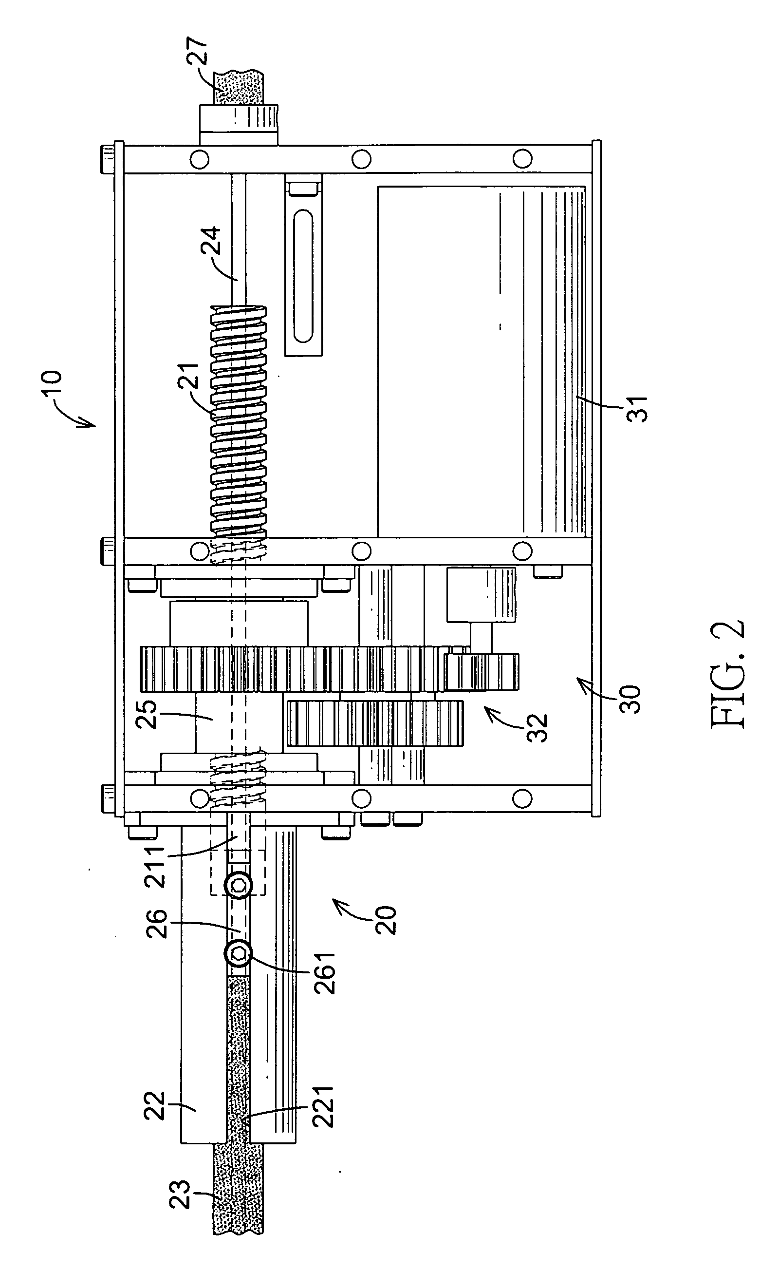
[0029]With reference to FIGS. 1, 2, 3 and 6, a driving device for a parking brake system in accordance with the present invention comprises a housing (10), a casing shift member (20), a break cable (24) mounted through the casing shift member (20) and a driving member (30).

[0030]The housing (10) can be mounting in a car for fastening the driving device.

[0031]The casing shift member (20) comprises at least one cable casing (23)(27) and the brake cable (24) is mounted through the at least one cable casing (23)(27). The casing shift member (20) may comprise a guide rod (21), a guide tube (22), a first cable casing (23), an inner threaded rod (25), a slide sleeve (26) and a second cable casing (27). The guide rod (21) is mounted movably in the housing (10), is mounted around the brake cable (24) and has a protruding end (211) and an outer thread. The guide tube (22) is connected to the housing (10), is mounted around the protruding end (211) of the guide rod (21) and has a longitudinal ...


PUM


Abstract

A driving device for a parking brake system includes a casing shift member, a brake cable and a driving member. The casing shift member includes a cable casing. The brake cable is mounted through the cable casing. The driving member has a driving unit connected to and driving the casing shift member to perform a longitudinal motion. Thus the cable casing applies a force on the brake cable so as to perform a brake work. Because the brake cable is tightened with the force provided by the cable casing, the brake cable is only bent slightly. Thus the curvature of the brake cable is small. That prevents the brake cable from being damaged and prolongs a life span of the brake cable. Moreover, a mechanical efficiency of the driving device is improved because the brake cable is tightened with the force provided by the cable casing.

Description

BACKGROUND OF THE INVENTION[0001]1. Field of Invention[0002]The present invention relates to a parking brake system, and more particularly to a driving device for a parking brake system that is durable and efficient.[0003]2. Description of the Related Art[0004]A conventional mechanical parking brake system (i.e. hand brake) comprises a lever in a car. When a driver pulls the lever for parking a car, brake mechanisms of the car are actuated to prevent the car from moving. However, due to the lever of the conventional mechanical parking brake system occupies a space in the car it does not conform to an electronic trend of a modern automobile industry.[0005]A conventional electronic parking brake system uses electronic controllers to control the driving device of the parking brake system, so users can use a button or the like to replace a lever for controlling the parking brake system. Conventional driving devices of an electronic parking brake system can be classed with a single cable...

Claims


Application Information

Patent Timeline
IPC IPC(8): B60L7/00
CPCB60T11/046B60T13/746Y10T74/20462F16H2025/2081Y10T74/2003F16H25/20
Inventor HUANG, CHIEN-TAICHEN, CHIEN-TZUCHENG, SHOU-TICHEN, BO-RUEIHUANG, MING-HU
Owner AUTOMOTIVE RES & TESTING CENT
Learn More