
Methods and apparatus for an integrated aerodynamic panel

a technology of aerodynamic panels and components, applied in the field of control panels, can solve the problems of increasing the number of fasteners and other components, increasing the cost, weight, assembly time, etc., and achieve the effect of decreasing the thickness

Active Publication Date: 2009-12-03
THE BOEING CO
View PDF10 Cites 23 Cited by
  • Summary
  • Abstract
  • Description
  • Claims
  • Application Information

AI Technical Summary

Benefits of technology

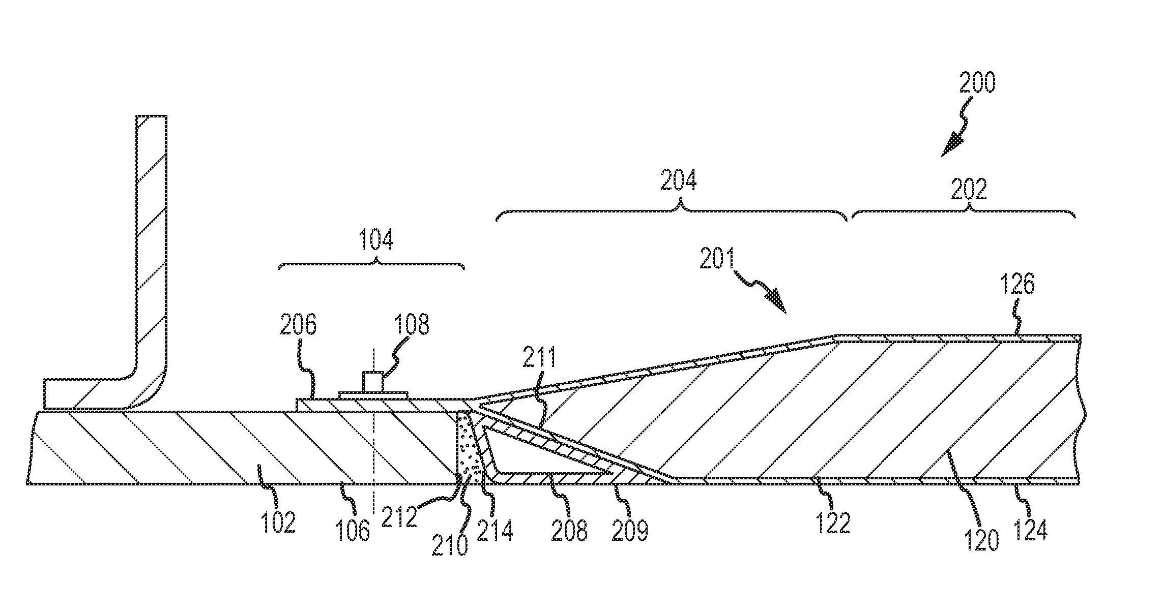
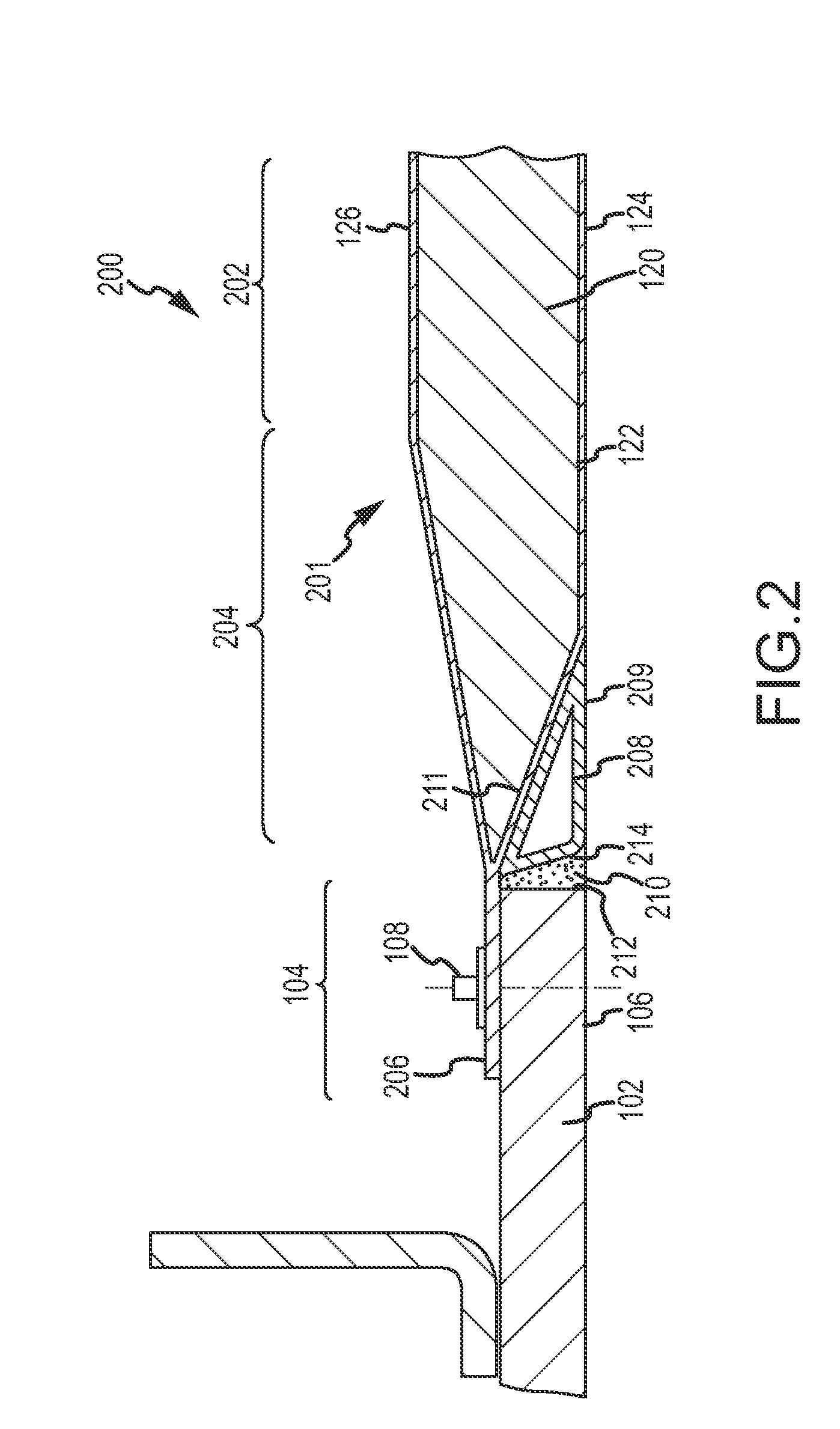
[0006]Methods and apparatus are provided for an integrated aerodynamic panel that includes a reduced set of components and can be attached in a simplified manner. In one embodiment, an integrated aerodynamic panel—e.g., for a trailing edge or leading edge of an aircraft surface—includes a first panel region having a first surface defining a outer mold line and a second surface, opposite the first surface, defining an inner mold line; a second panel region contiguous with and extending from the first panel region, the second panel region having a thickness that decreases as it extends from the first panel region; a splice plate region extending from the second panel region, the edge band region configured to accept a fastener; and a filler region adjacent the second panel region and having an exposed surface substantially flush with the outer mold line.
[0007]In accordance with another embodiment, an aerodynamic panel system includes a skin panel having an edge band defined thereon and an integrated aerodynamic panel. The integrated aerodynamic panel includes a first panel region having a first surface defining a outer mold line and a second surface, opposite the first surface, defining an inner mold line. A second panel region is contiguous with and extends from the first panel region, and the second panel region has a thickness that decreases as it extends from the first panel region. A splice plate region extends from the second panel region. A filler region adjacent the second panel region has an exposed surface substantially flush with the outer mold line. A plurality of fasteners is configured to rigidly attach the splice plate region of the integrated aerodynamic panel to the edge band region.
[0008]In accordance with another embodiment, a method for forming an aerodynamic panel assembly includes the steps of providing an aircraft skin panel having an edge band defined thereon, forming a first panel region contiguous with a second panel region, wherein the first panel region has a first surface defining a outer mold line, and the second panel region is contiguous with and extends from the first panel region such that it has a gradually decreasing thickness; forming a splice plate region extending from the second panel region; forming a filler region and bonding it to the second panel region such that the filler region has an exposed surface substantially flush with the outer mold line; and fastening the splice plate region of the integrated aerodynamic panel to the edge band of the skin panel via a plurality of fasteners.

Problems solved by technology

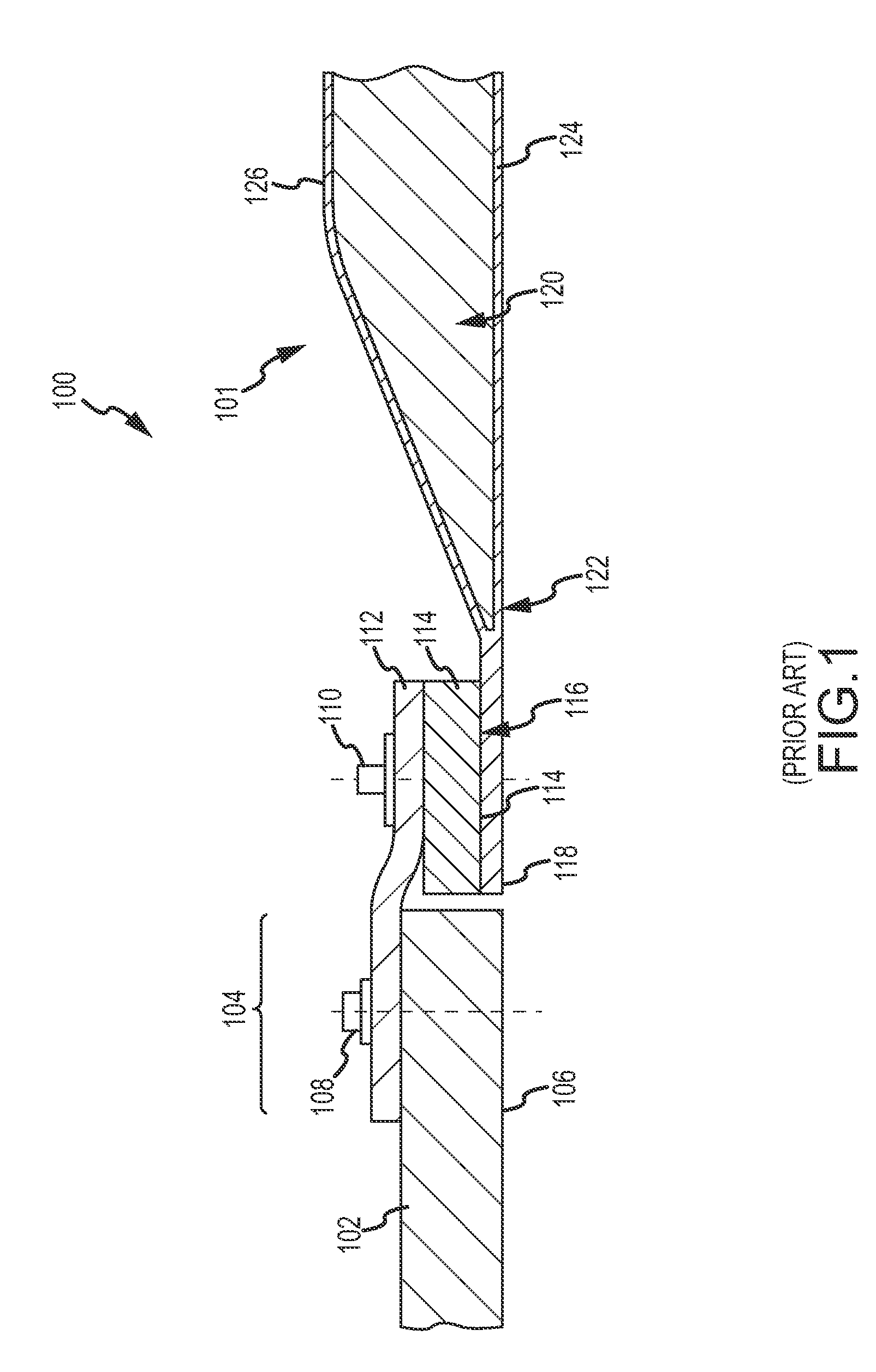
The large number of fasteners and other components tends to increase cost, weight, and assembly time.

Method used


Image

  • Methods and apparatus for an integrated aerodynamic  panel
  • Methods and apparatus for an integrated aerodynamic  panel
  • Methods and apparatus for an integrated aerodynamic  panel

Examples


Embodiment Construction

[0013]In general, what is described is an aerodynamic panel that has an integrated filler region that maintains a continuous aerodynamic surface (or a continuity of the surface 106-124) and an edge band that may be directly affixed to a skin panel or the like. In this way, an entire row of fasteners is removed, and the overall weight, cost, and complexity of the assembly is reduced.

[0014]The following detailed description is merely exemplary in nature and is not intended to limit the described embodiments or the application and uses of the described embodiments. Furthermore, there is no intention to be bound by any expressed or implied theory presented in the preceding technical field, background, brief summary or the following detailed description.

[0015]For simplicity and clarity of illustration, the drawing figures depict the general structure and / or manner of construction of the various embodiments. Descriptions and details of well-known features and techniques may be omitted to ...


PUM

PropertyMeasurementUnit
thicknessaaaaaaaaaa
thickaaaaaaaaaa
weightaaaaaaaaaa

Abstract

An integrated aerodynamic panel—e.g., for a trailing edge or leading edge of an aircraft aerodynamic surface—includes a first panel region defining inner and outer mold lines, and a second panel region contiguous with and extending from the first panel region in a tapering fashion. A splice plate region extends from the second panel region and includes an edge band region configured to accept a fastener. A filler region (e.g., a SYNCORE or fiberglass structure) adjacent the second panel region has an exposed surface substantially flush with the outer mold line.

Description

TECHNICAL FIELD[0001]The embodiments described herein generally relate to control panels used in connection with aircraft and the like, and more particularly relate to methods and apparatus for an integrated aerodynamic panel.BACKGROUND[0002]Aircraft generally include a number of aerodynamic panels distributed over various structures—e.g., along the trailing edge (TE) and leading edge (LE) of the wings, the horizontal stabilizer, and / or the vertical stabilizer of an aircraft. Such assemblies typically include a secondary panel that is secured (permanent or removable) to a main box skin panel.[0003]More particularly, with reference to the cross-sectional diagram shown in FIG. 1, a traditional panel assembly 100 generally includes a secondary panel 101 coupled to a relatively thick skin panel (or “main box” skin panel) 102. Panel 101 has an inner mold line (IML) 126 and outer mold line (OML) 124, and generally includes a core 120 bounded by thin skin plies 122. Panel 101 tapers to a r...

Claims


Application Information

Patent Timeline
Patent Type & Authority Applications(United States)
IPC IPC(8): B64C1/00B64C3/28B23P19/04
CPCB64C1/12B64C3/26Y10T29/49838B64C5/06B64C5/02
Inventor BERRY, ELDON R.MUNDEL, JOHN E.ANDRYUKOV, VLADISLAY
Owner THE BOEING CO
Learn More