Projector mount with phillips screw driver angle adjustment

a projector mount and screw driver technology, applied in washstands, curtain suspension devices, lighting support devices, etc., can solve the problems of increasing the mounting not allowing finite positioning of the projected beam, and creating additional height and complexity of the projector mount, so as to reduce the cost of production and cost

Inactive Publication Date: 2009-12-03
SPECIALTY FINANCE
View PDF28 Cites 37 Cited by
  • Summary
  • Abstract
  • Description
  • Claims
  • Application Information

AI Technical Summary

Benefits of technology

[0011]It is still another object of the projector mount to produce a projector mount is a more cost effective price. The elimination of parts, or the combination of parts, is the most effective means to reduce the cost of production. Cost reduction is often accomplished with the loss of functionality. In the pending application the rack is formed into existing structure and the pinion gear is provided using the cross head screw driver that an installer would normally use to install the projector mount. All of the desired features remain in the pending application with a lower cost of manufacturing.

Problems solved by technology

The use of gears improved the installers' ability to make minor changes, but the addition of the gears increased the mounting height and complexity of the projector mount.
While these patents disclose adjustable projector mounts, because of the backlash that is associated with frictional systems these mounts do not allow for finite positioning of the projected beam of a projector.
There are no provisions to alter the side to side orientation and because of mechanical backlash re-positioning of the projector would require several attempts.
The inclusion of the gears makes angular adjustment simpler with minimal backlash, but the integration of the gears, rack and pinion creates additional height and complexity to the projector mount.

Method used


Image

  • Projector mount with phillips screw driver angle adjustment
  • Projector mount with phillips screw driver angle adjustment
  • Projector mount with phillips screw driver angle adjustment

Examples


Embodiment Construction

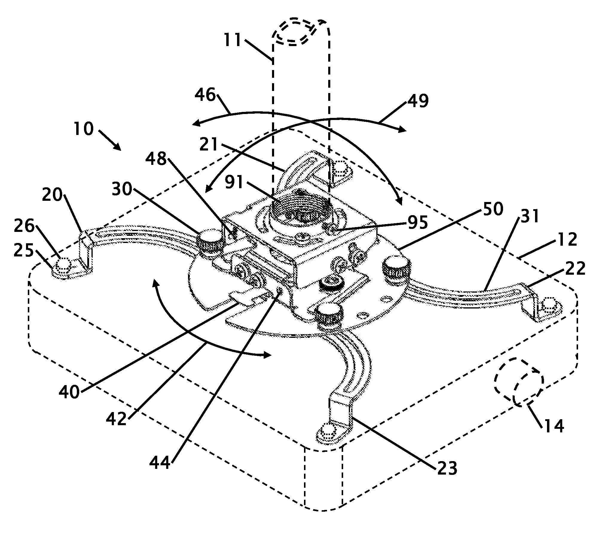
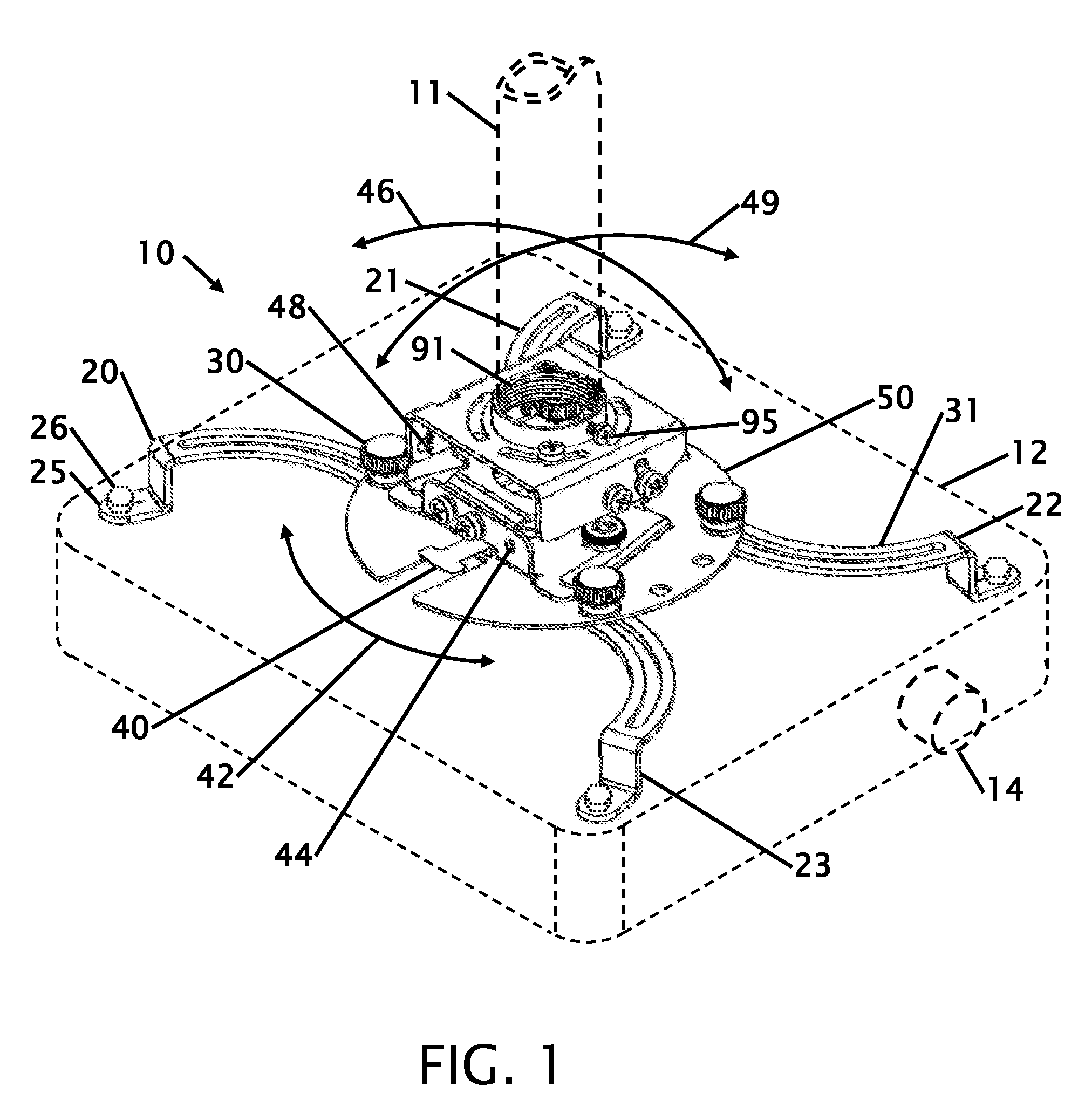
[0020]FIG. 1 shows an isometric view of the projector mount showing the mount 10 on a ceiling extension tube and a LCD type projector 12 having a lens 14 that projects and image onto a screen or wall. This figure shows an LCD type projector mounted on a down tube 11, but the projector 12 could be mounted on a floor mounted post in an inverted orientation or on a side wall if desired. The down tube 11 is secured into a pipe thread and is locked from rotation with a set screw 95. The projector is secured or screwed into the projector with bolts 26, screws or the like. The securing mechanism is with a series of arms 20-23 that terminate on feet 25. The arms 20-23 are adjustably secured to the base 50 with slots 31 that are secured with a thumb screw 30 or similar securing means. The direction and angle of the projector 12 is adjustable. A yaw 42 adjustment is made by pushing a taw adjust tab 40 to one side or another. The yaw adjustment allows the projector to be side-to-side without m...


PUM


Abstract

Improvements in a mount for attaching a television of projector to an overhead or ground structure is disclosed. The mount allows for spin, side to side and front to back angle adjustment. The adjustment components are formed from the present projector mount uses metal component having a rack comprising a plurality of formed teeth that are engageable in the recessed side of a crosshead screwdriver that is trademarked as a Phillips screwdriver. The recesses of the crosshead screwdriver act as a pinion gear in the rack to adjust the mounted angle of a projector on the projector mount. This configuration reduces parts count, size and cost without compromising functionality. The axis of rotation of both the side-to-side and front-to-back pass through the projector mount.

Description

FIELD OF THE INVENTION[0001]This invention relates to improvements in an adjustable projector mount. More particularly, the present projector mount uses metal component having a rack comprising a plurality of formed teeth that are engageable in the recessed side of a crosshead screwdriver that is trademarked as a Phillips screwdriver. The recesses of the crosshead screwdriver act as a pinion gear in the rack to adjust the mounted angle of a projector on the projector mount.BACKGROUND OF THE INVENTION[0002]Television and computer projectors are either placed on a table or are mounted to the ceiling. When these devices are mounted they must often be adjusted to project the image onto a screen or wall. The adjustment often requires changing the vertical and or rotational angle of the projector. Minor angular changes will have a great effect on where the image is being shown because the distance from the adjustment point to the pivot is amplified based upon the distance the image is bei...

Claims


Application Information

Patent Timeline
Patent Type & Authority Applications(United States)
IPC IPC(8): A47H1/10
CPCF16M11/04F16M11/043F16M13/02F16M11/18F16M11/2035F16M11/12
Inventor DAVID, MIKE
Owner SPECIALTY FINANCE
Why Eureka
Try Eureka