

Mass spectrometer and mass spectrometry method
a mass spectrometer and mass spectrometry technology, applied in the direction of isotope separation, electric discharge tubes, separation processes, etc., can solve the problem of accurate mass dissociation of the second stage, and achieve the effect of trap capacity and mass accuracy
- Summary
- Abstract
- Description
- Claims
- Application Information
AI Technical Summary
Benefits of technology
Problems solved by technology
Method used
Image

Examples
embodiment 1
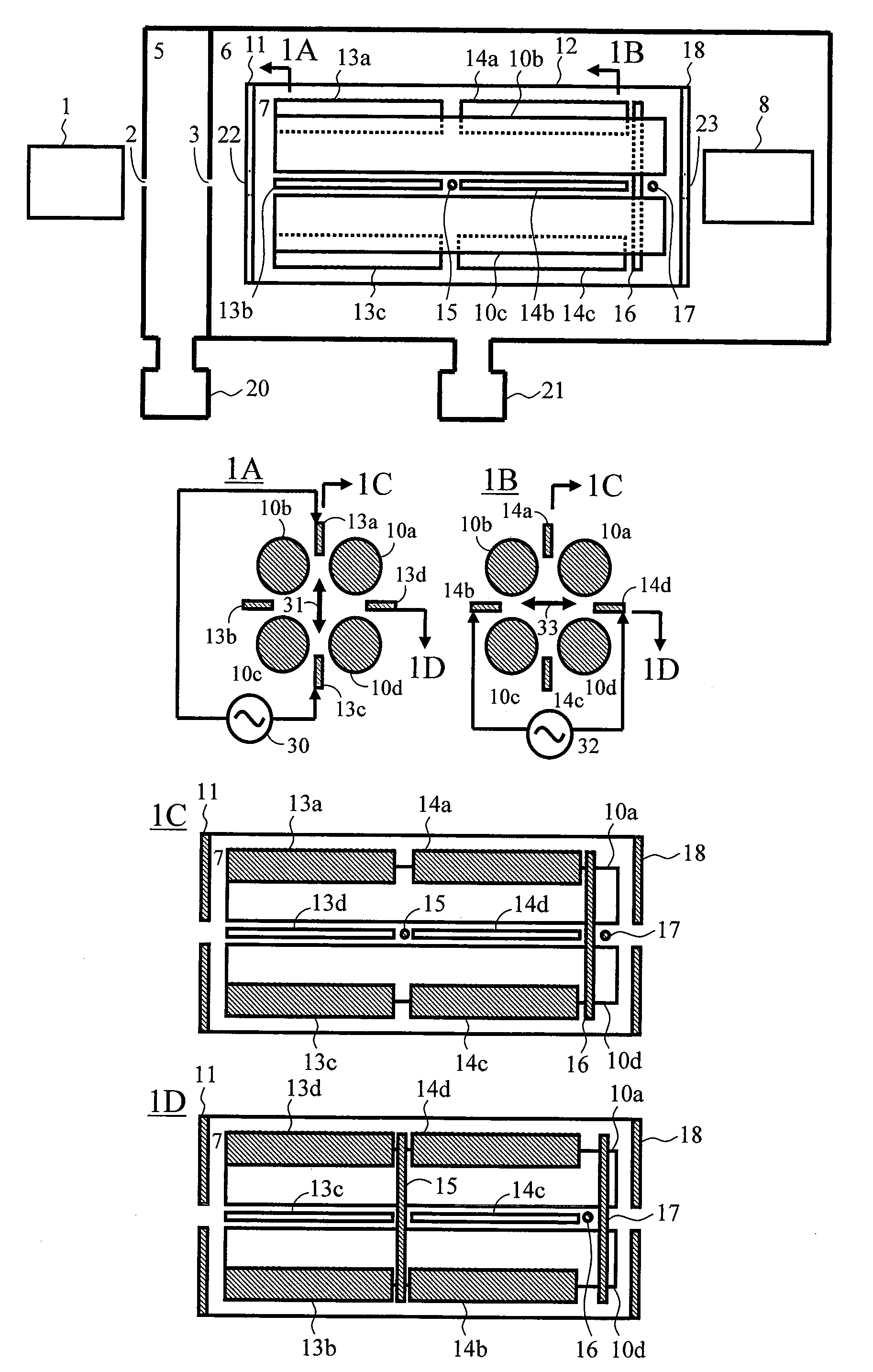
[0091]FIG. 1 is a configuration diagram of a linear ion trap to which the present system is applied. Ions generated at an ion source 1 pass through a first orifice 2, and are introduced into a differential pumping region 5 that is evacuated by a vacuum pump 20. Then, the ions pass through a second orifice 3, and are introduced into a vacuum chamber 6 that is evacuated to 10−6 Torr to 10−4 Torr by a vacuum pump 21. Then, the ions pass through an orifice 22, and are introduced into a linear ion trap chamber 7. The linear ion trap chamber 7 is enclosed by an end electrode (inlet electrode) 11, an outer cylinder 12, and an end electrode (exit electrode) 18, and a gas is introduced thereinto by a gas supplying portion (not shown). A noble gas, such as helium, argon or the like, nitrogen, or the like is used as the supplied gas, and the pressure in the linear ion trap chamber 7 is maintained at approximately 10−4 Torr to 10−2 Torr. The ions introduced into the linear ion trap chamber 7 ar...
embodiment 2
[0093]FIG. 4 is a configuration diagram of a second embodiment of a linear ion trap to which the present system is applied. The system from the ion source up to the first ion trap portion is similar to Embodiment 1. In Embodiment 2, the trap is divided into three parts. RF voltages (approximately 1 MHz, ±5 kV) whose phases are inverted alternately are applied to each of quadrupole rods 40, 41, and 42. As a result, a pseudo harmonic potential is formed in a radial direction that is orthogonal to the axial-direction of the rods. Further, a voltage of approximately 2-30 V with respect to the quadrupole rods is applied to wire electrodes 43 and 44, and end electrodes (inlet and exit electrodes) 11 and 18, thus making accumulation in the axial direction possible in each ion trap portion. By using vane electrodes, ions can be resonantly excited in the center directions (31 and 33) of the quadrupole rods. However, by superimposing supplemental AC voltages 45, 47, and 49 on the quadrupole r...
embodiment 3
[0094]FIG. 5 is a configuration diagram of a third embodiment of a linear ion trap to which the present system is applied. In Embodiment 1 and Embodiment 2, ion traps of a type in which a wire electrode is used in the first ion trap portion were used. However, the present embodiment uses a linear ion trap of a type in which a fringing field that occurs between quadrupole rods and an end electrode is used in the first ion trap portion. In this embodiment, too, the path by which ions travel from the ion source up to the first ion trap portion comprising end electrodes 52 and 54, as well as quadrupole rods 53 is similar. RF voltages (approximately 1 MHz, ±5 kV) whose phases are inverted alternately are applied to the quadrupole rods 53. As a result, a pseudo harmonic potential is formed in a radial direction that is orthogonal to the axial direction of the rods. Further, a voltage of approximately 2-30 V with respect to the quadrupole rods is applied to the end electrodes 52 and 54, th...
PUM
 Abstract
Description
Claims
Application Information