Source driver for display panel and drive control method

a technology of source driver and display panel, applied in the direction of instruments, computing, electric digital data processing, etc., can solve the problems of difficulty in accurately detecting between frames and otherwise affecting image quality, and achieve the effect of good display quality

Active Publication Date: 2009-12-03
LAPIS SEMICON CO LTD
View PDF9 Cites 18 Cited by
  • Summary
  • Abstract
  • Description
  • Claims
  • Application Information

AI Technical Summary

Benefits of technology

[0010]According to the present invention, a pseudo vertical synchronization signal can be generated without a vertical synchronization signal of the image signal being fed to the source driver, and the offset voltage component of t

Problems solved by technology

Nonuniform display occurs or image quality is otherwise negatively affected when an offset voltage is included in the drive voltage.
However, the vertical synchroniza

Method used


Image

  • Source driver for display panel and drive control method
  • Source driver for display panel and drive control method
  • Source driver for display panel and drive control method

Examples


Embodiment Construction

[0029]Embodiments of the present invention are described in detail below with reference to the drawings.

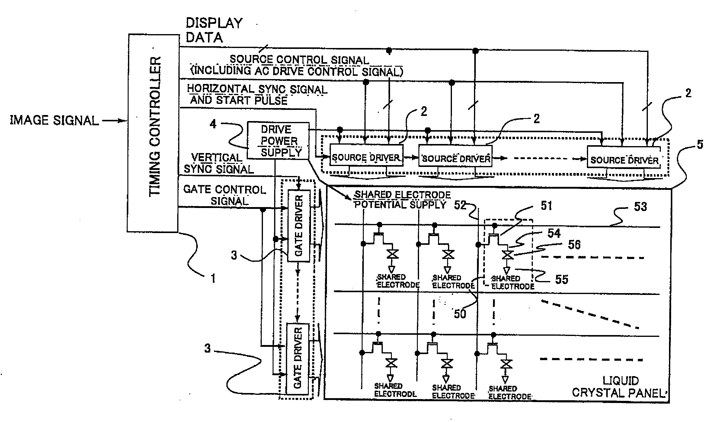
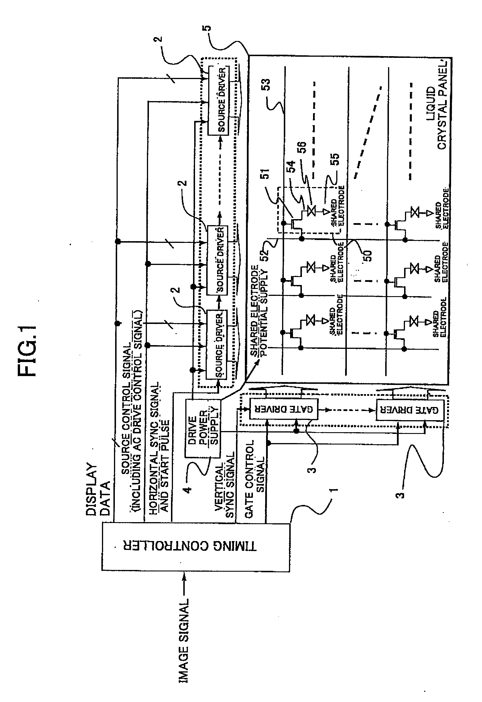
[0030]FIG. 1 shows a liquid crystal display device as an example of the present invention. The liquid crystal display device is provided with a timing controller 1, a plurality of source drivers 2, a plurality of gate drivers 3, a drive power supply 4, and a TFT liquid crystal panel 5.

[0031]The TFT liquid crystal panel 5 is provided with a plurality of source signal lines 52 extending in the column direction and a plurality of gate signal lines 53 extending in the row direction, and cells (pixels) are formed by the intersecting portions between the source signal lines 52 and the gate signal lines 53. Each cell is schematically shown in FIG. 1 and is provided with a TFT (thin-film transistor) 51 and a liquid crystal element 56. The source of the TFT 51 is connected to the source signal line 52, and the gate is connected to the gate signal line 53. One end (element electrode) 54 of ...


PUM


Abstract

A source driver and drive control method therefor that makes it possible to cancel offset voltages and to obtain good display quality even when a vertical synchronization signal is not fed to the source driver. A source driver is provided for receiving from a timing controller a horizontal synchronization signal of an image signal, and a binary control signal of which a value varies in two values in synchronization with the horizontal synchronization signal and in which start values of adjacent frames of the image signal are different, excluding a vertical synchronization signal of the image signal, to apply a drive voltage to a plurality of source signal lines of a display panel. In the source driver, the vertical cycle of the image signal is analyzed on the basis of the binary control signal; a pseudo vertical synchronization signal is generated on the basis of the vertical cycle; and a cancel operation of an offset voltage component of the drive voltage is perform on the basis of the pseudo vertical synchronization signal.

Description

BACKGROUND OF THE INVENTION[0001]1. Field of the Invention[0002]The present invention relates to a source driver for a display panel such as an active matrix liquid crystal panel and a drive control method therefor.[0003]2. Description of the Related Art[0004]It is known that AC driving is required in order to assure long-term reliability of a liquid crystal panel. Accordingly, in a conventional active matrix liquid crystal display device, the polarity of the drive voltage applied by a source driver between the electrodes of a liquid crystal element of each cell (pixel) of the liquid crystal panel is inverted for each frame of the image signal (see Japanese Laid-open Patent Application No. 2002-108303). Rather than simultaneously setting all cells of the liquid crystal panel to the same polarity, there is used a dot inversion drive-scheme, in which the cells in adjacent columns and rows become inverted in polarity, or a two-line dot inversion method, in which every two lines are inv...

Claims


Application Information

Patent Timeline
IPC IPC(8): G09G5/00
CPCG09G3/3614G09G3/3688G09G2320/0233G09G2310/027G09G2300/0426
Inventor WANG, HAISONG
Owner LAPIS SEMICON CO LTD
Why Eureka
Try Eureka