Support devices for catheters

a technology for supporting devices and catheters, which is applied in the direction of intravenous devices, infusion devices, infusion needles, etc., can solve the problems of increasing the likelihood of infection around the catheter site, not being able to easily remove or reposition the catheter, and the patient's discomfort in the removal of the tape, so as to facilitate the application of the device to the patient, the effect of enhancing the grip

Inactive Publication Date: 2009-12-03
EAST & NORTH HERTFORDSHIRE NHS TRUST
View PDF3 Cites 21 Cited by
  • Summary
  • Abstract
  • Description
  • Claims
  • Application Information

AI Technical Summary

Benefits of technology

[0027]The material used to make the device as a whole, or alternatively just the gripping member(s), may also be provided with a degree of elasticity, to enhance the grip between the device and the catheter(s).
[0028]Preferably the underside of the base member incorporates adhesive for attaching the device to the patient's body in use. This facilitates the application of the device to the patient.

Problems solved by technology

In use, catheters are liable to be pulled accidentally, which can result in an injury or even a medical emergency for the patient, a potentially critical loosening of the cuffs around the catheter tube, or an increased likelihood of infection around the catheter site.
However, such tape may normally only be used once, and does not readily allow the catheter to be removed or repositioned without cutting or removing the tape.
Removal of the tape can be uncomfortable for the patient, particularly if the adhesive on the tape has become stuck to the patent's body hair.
Furthermore, adhesive from the tape can remain stuck on the outside of the catheter, causing the catheter to become sticky and unsightly, and ultimately harder to keep clean and maintain the standard of hygiene required in a medical environment.
Such discs have proved to be uncomfortable for patients, particularly at the instance when a catheter line is pressed onto a disc.
These discs are generally only suitable for single use, since the catheter line cannot be readily removed.
Additionally, because the retaining clips are of a fixed shape and configuration, and because catheters tubes are available in a range of external diameters, it has been found that the discs are unable to hold some catheter lines sufficiently securely, and that the lines are still prone to slipping.
It is also possible to damage some catheter lines when pressing them into the retaining clips.
A further problem may be encountered by a medical professional when installing a pair of catheter lines for haemodialysis.
The two catheter lines are normally attached concurrently to the patient, but manipulating the two lines simultaneously can be cumbersome and awkward.
Additionally, if the catheter lines are placed in contact with one another and attached to the patient's body by tape enveloping both the lines, the lines (being plastic) are prone to slip against each other beneath the tape, and this can lead to the lines becoming disconnected from the patient.
This is not only dangerous for the patient, due to the accidental loss of blood, but also exposes the patient to an increased risk of infection.

Method used


Image

  • Support devices for catheters
  • Support devices for catheters
  • Support devices for catheters

Examples


first embodiment

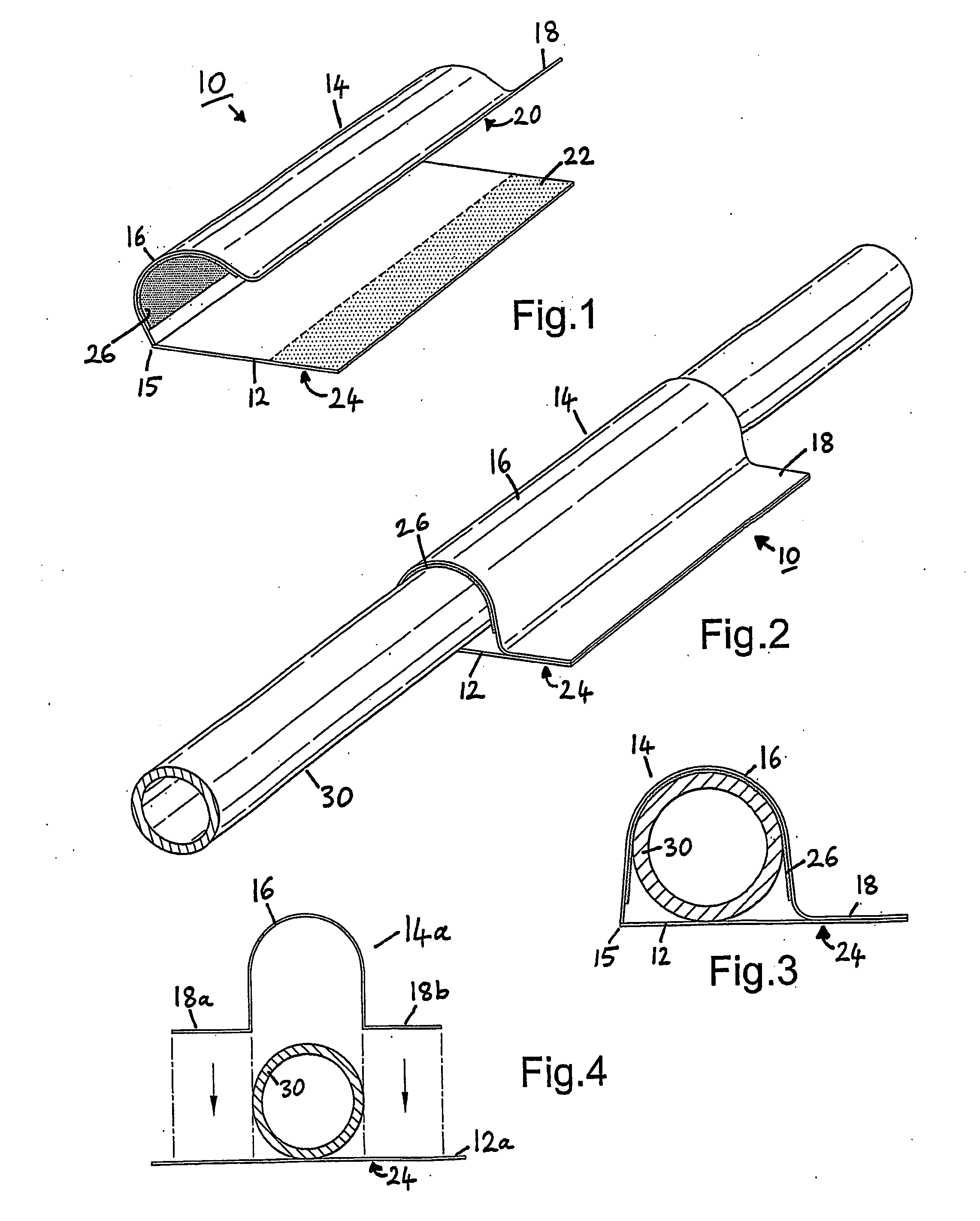
[0048]FIG. 1 illustrates a support dressing or support device 10 for use with a single catheter tube. The device 10 comprises a base member 12 and a gripping member 14. In this illustrated embodiment, the gripping member 14 is pre-attached by a flexible fold, hinge or seam to the base member 12, such that the gripping member 14 may be closed onto the base member 12 in use.

[0049]The base member 12 is formed of a generally flat piece of material, which is preferably flexible, that is attachable to a patient's body in use.

[0050]The gripping member 14 is of the general form of a strap or cover, which is preferably flexible. The gripping member 14 comprises an attachment region 18, of which the underside 20 is attachable to the base member 12—for example attaching to region 22 of the base member. Between the end 15 and the attachment region 18, the gripping member 14 incorporates an intermediate region 16 that is adapted to wrap over a catheter in use.

[0051]As illustrated in FIG. 1, the ...

second embodiment

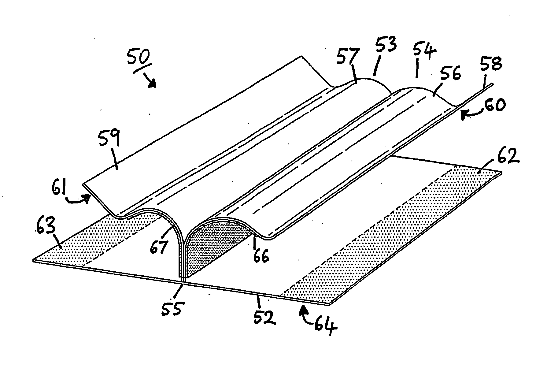
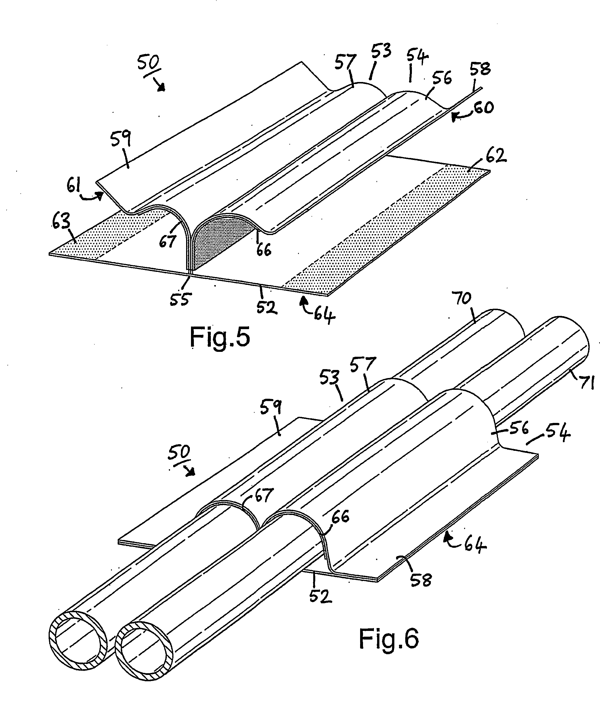
[0057]FIG. 5 illustrates a support dressing or support device 50, for use with a pair of catheter tubes. Here, the device 50 comprises a base member 52 and a pair of gripping members 53, 54. The gripping members 53, 54 are preferably made from a single piece of material, and are pre-attached to the base member 52 via a flexible hinge or seam region 55. The seam or hinge 55 may be formed by a line of stitching or adhesive, and is aligned parallel to the orientation of the catheters in use. The device 50 is substantially symmetrical about the seam or hinge 55.

[0058]The general features and principle of operation of the second embodiment are substantially the same as those of the first embodiment.

[0059]As with the first embodiment, the gripping members 53, 54 are preferably of the general form of flexible straps or covers. Each gripping member 53, 54 comprises a respective attachment region 59, 58, of which the undersides 61, 60 are attachable to the base member 52—for example attachin...

third embodiment

[0083]FIGS. 12 & 13 illustrates a support dressing or support device 130 for use with one or more catheter tubes.

[0084]Here, the gripping members 53, 54 are connected to either side of the base member 52. The gripping members 53,54 may be integral with or attached to the base member 52 via a flexible hinge or seam region.

[0085]The gripping members 53, 54 extend from protrusions on either side of the base member 52. As with the first and second embodiment, the gripping members 53, 54 are preferably of the general form of flexible straps or covers. However, the attachment regions 58, 59 are attachable to a patent's body.

[0086]In use, each gripping member 53, 54 is extended over a catheter placed on the base member 52 and then attached to the patent's body at the attachment regions 58, 59, as illustrated in FIG. 13.

[0087]As discussed previously, the gripping members 53, 54 are provided with intermediate region 56, 57 between the connection to the base member 52 and the attachment regio...


PUM


Abstract

A device for securing a catheter tube against a patient's body, said device comprising a base member for attaching to the patient's body in use, and a gripping member, the gripping member comprising: a first region that is attached to, or attachable, to, or integral with, the base member; an attachment region that is attachable to the base member; and an intermediate region between the first region and the attachment region, the intermediate region being adapted to wrap over a catheter tube; the device being arranged such that, in use, the first region of the gripping member is attached to the base member, the intermediate region is wrapped over a catheter tube, and the attachment region is attached to the base member, thereby securing the catheter tube between the base member and the gripping member. Also provided is a device for securing two catheter tubes against a patient's body, said device comprising a base member for attaching to the patient's body in use, and two gripping members, each gripping member comprising: a first region that is attached to, or attachable to, or integral with, the base member; an attachment region that is attachable to the base member; and an intermediate region between the first region and the attachment region, the intermediate region being adapted to wrap over a catheter tube; the device being arranged such that, in use, the first region of each gripping member is attached to the base member, the intermediate region of each gripping member is wrapped over a respective catheter tube, and the attachment region of each gripping member is attached to the base member, thereby securing the two catheter tubes between the base member and the respective gripping members. This device is particularly suited for use with single or dual-lumen catheters, for example as used in haemodialysis.

Description

BACKGROUND OF THE INVENTION[0001]This invention relates to devices for securing catheters against patients' bodies. The invention is particularly suitable, but by no means limited, for use with tunnelled central venous catheters such as those used for haemodialysis.[0002]A catheter is a hollow flexible tube, usually made of plastic, for insertion into a body cavity, duct, or vessel. Catheters may be used for a variety of medical purposes, examples of which include insertion into a lumen of a blood vessel for performing haemodialysis or to administer an injection, drainage of urine from the bladder through the urethra, or insertion through a blood vessel into the heart for diagnostic purposes.[0003]For haemodialysis, a pair of tunnelled central venous catheters (CVCS) such as the Tesio catheter system, or a dual-lumen catheter (e.g. HemoSplit™ or Ash Split), may be used. Each catheter tube (or “line”) is commonly inserted into a lumen of a vein (e.g. internal jugular vein, subclavian...

Claims


Application Information

Patent Timeline
Patent Type & Authority Applications(United States)
IPC IPC(8): A61M25/02
CPCA61M2025/026A61M25/02
Inventor PINKUS, LESLEY RUTH
Owner EAST & NORTH HERTFORDSHIRE NHS TRUST
Why Eureka
Try Eureka