Filter bag

Inactive Publication Date: 2009-12-10
WOLF PVG GMBH & CO KG
View PDF15 Cites 14 Cited by
  • Summary
  • Abstract
  • Description
  • Claims
  • Application Information

AI Technical Summary

Benefits of technology

[0017]To be able to secure the filter insert effectively inside the filter bag during a running production process, the filter insert can

Problems solved by technology

Once a vacuum cleaner bag of this type is loaded with dust, the dust will clog the filter material layers, thereby resulting in a reduction of the volume flow and thus also in a drop in the suction capacity.
To be sure, a separati

Method used


Image

  • Filter bag
  • Filter bag
  • Filter bag

Examples


Embodiment Construction

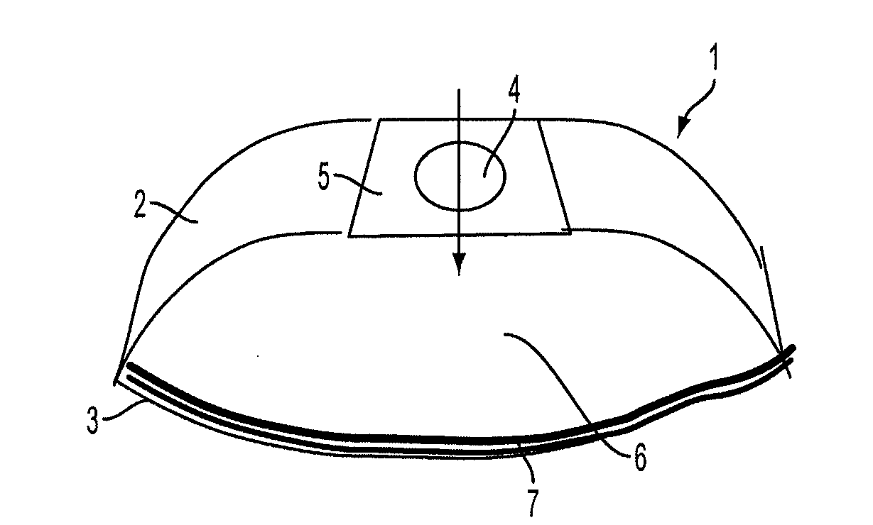
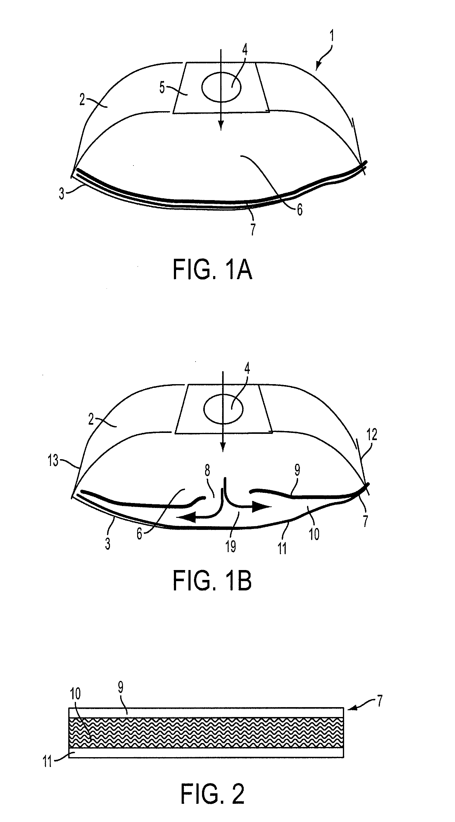
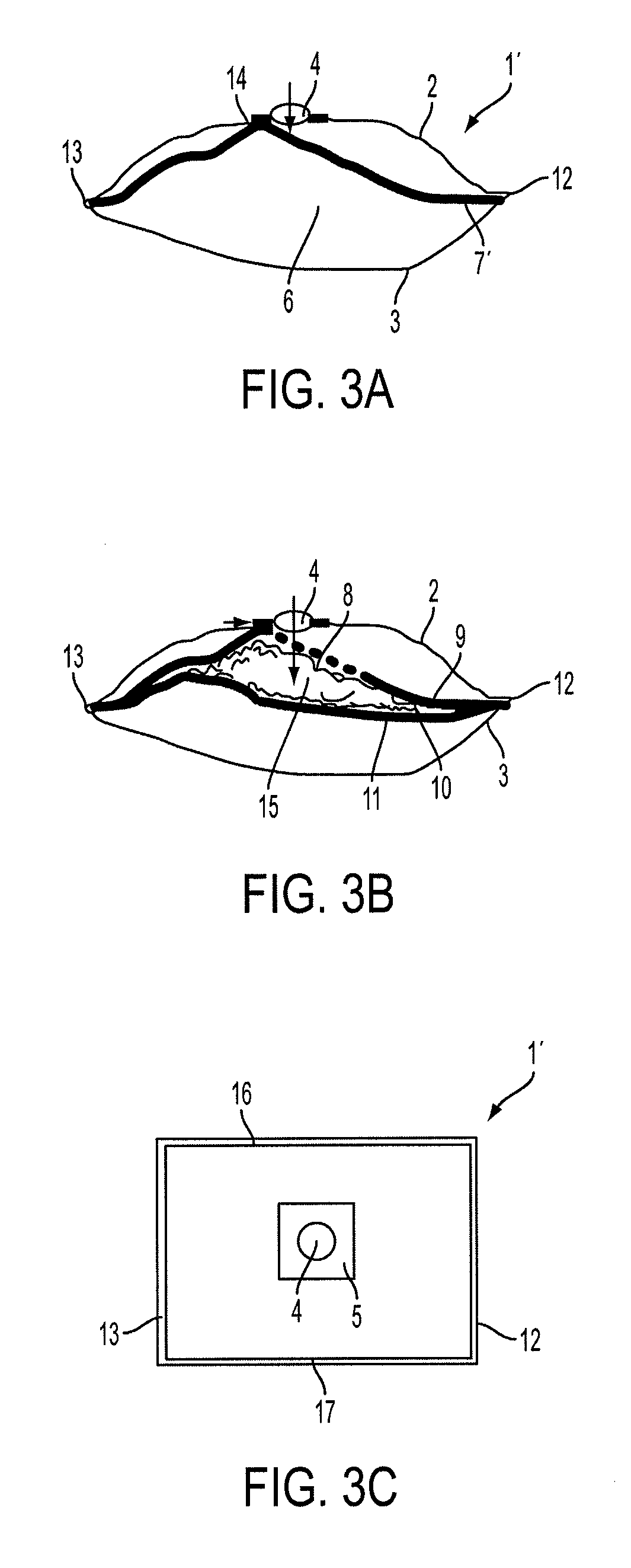
[0024]Referring to FIGS. 1A and 1B there is shown a filter bag 1 which comprises a first upper filter material layer 2 with an inflow opening 4 embodied therein. The first filter material layer 2 is connected on all sides along the edges to a second filter material layer 3, for example with the aid of a welded seam. The filter material layers 2 and 3 can be composed of a multi-layer nonwoven material, which is provided with at least one micro-filter layer, for example a meltblown layer.

[0025]Around the inflow opening 4, a holding disc 5 is provided for attaching the filter bag 1 to a vacuum cleaner. An inside space 6 in which dust can collect during the operation is embodied between the first filter material layer 2 and the second filter material layer 3.

[0026]To increase the dust collection capacity of the filter bag 1, an inside space 6 is provided with a filter insert 7 that rests fully on the second filter material layer 3 and is attached along the edge to the seam between the f...


PUM

PropertyMeasurementUnit
Thicknessaaaaaaaaaa
Thicknessaaaaaaaaaa
Fractionaaaaaaaaaa

Abstract

A filter bag includes a first filter material layer including an inflow opening, a second filter material layer having edges along which the second filter layer is joined to the first filter material layer to form an inside space; and a flat, multi-layer filter insert arranged in the inside space and having sections connected, respectively, to the first and second material layers. The filter insert has at least two outer layers defining an intermediate area there between. The intermediate area includes a center layer or an intermediate space for dust collection.

Description

CROSS-REFERENCE TO RELATED APPLICATION[0001]This application claims the priority of German Patent Application No. 20 2008 007 717.6, filed on Jun. 10, 2008, the subject matter of which is incorporated herein by reference.BACKGROUND OF THE INVENTION[0002]The present invention relates to a filter bag, in particular used for vacuum cleaners, consisting of a first filter material layer with an inflow opening and a second filter material layer, which is connected along the edges to the first filter material layer to form an inside space, wherein a multi-layer, flat filter insert is arranged on the inside and is joined at least in some sections to the first, respectively the second, filter material layer.[0003]German patent document DE 20 2005 009 945 discloses a vacuum cleaner bag, having an upper filter material layer that is welded along the edges to a lower filter material layer. An inflow opening is formed in one filter material layer, wherein a cushion with material for absorbing un...

Claims


Application Information

Patent Timeline
IPC IPC(8): B01D46/02
CPCA47L9/14B01D39/1676B01D39/1692Y10S15/08B01D39/2082B01D2239/065Y10S55/02B01D39/2017
Inventor ROSEMEIER, BRIGITTECZADO, WOLFGANG
Owner WOLF PVG GMBH & CO KG
Why Eureka
Try Eureka