Frequency tuning of disc resonator gyroscopes via resonator mass perturbation based on an identified model

a technology of disc resonator gyroscope and mass perturbation, which is applied in the direction of acceleration measurement using interia force, turn-sensitive devices, instruments, etc., can solve the problems of reducing energy dissipation, difficult to do compact, low-cost electronics, and local variations in etch rate that produce very small, so as to improve degeneracy and improve degeneracy

Active Publication Date: 2009-12-10
RGT UNIV OF CALIFORNIA +1
View PDF5 Cites 14 Cited by
  • Summary
  • Abstract
  • Description
  • Claims
  • Application Information

AI Technical Summary

Benefits of technology

[0019]A typical method of tuning a resonator comprises measuring a frequency response matrix of the resonator, the frequency response matrix having a plurality of inputs and a plurality of outputs and the resonator having a plurality of coupled resonance modes, fitting a structural mechanics model of the resonator to the frequency response matrix to identify parameters of the structural mechanics model including mass, damping, and stiffness matrices and their sensitivity to mass perturbation, and estimating an amount of the mass perturbation to the resonator to improve degeneracy of the plurality of coupled resonance modes based on the identified mass and the stiffness matrices and the determined sensitivity to the mass perturbation. The mass perturbation may comprise removing mass by a laser ablation process and / or adding mass by a mass deposition process. Typically, the parameters of the structural mechanics model further include an R matrix reflecting signal conditioning and non-colocation in operating the resonator.
[0021]Further, in some embodiments the resonator may be a disc resonator comprising a plurality of concentric interconnected rings. Typically, the plurality of coupled resonance modes may be Coriolis coupled modes of the disc resonator. Further, interconnections between the rings may be aligned to form spokes and the estimated amount of the mass perturbation may be estimated on two of the spokes closest one of axes of antinodes of the coupled resonance modes of the disc resonator. In this case, the estimated amount of the mass perturbation may be created on a first and then a second of the two spokes closest the one of the axes of the antinodes of the coupled resonance modes of the disc resonator and re-measuring the frequency response matrix of the resonator after creating the estimated amount of the mass perturbation to each of the first and the second of the two spokes. The antinodes of the coupled resonance modes may comprise high frequency antinodes and low frequency antinodes and creating the amount of the mass perturbation may comprise adding mass to the first and then the second of the two spokes closest the axes of the high frequency antinodes of the disc resonator. Alternately, the antinodes of the coupled resonance modes may comprise high frequency antinodes and low frequency antinodes and creating the amount of the mass perturbation may comprise removing mass to the first and then the second of the two spokes closest the axes of the low frequency antinodes of the disc resonator. Data of the measured and re-measured frequency response matrix may be used to fit the structural mechanics model of the resonator to redetermine parameters of the structural mechanics model including the mass, the damping, and the stiffness matrices, and further including a mass change at each of the two spokes. Estimating the amount of the mass perturbation to the disc resonator to improve degeneracy of the plurality of coupled resonance modes may comprise solving for the mass change at each of the two spokes to improve degeneracy based on the redetermined parameters of the structural mechanics model.

Problems solved by technology

Furthermore, the high degree of isolation reduces energy dissipation in the modes, which is a source of angular rate bias and drift.
For those sensors lending themselves to MEMS fabrication, such as the SiDRG, local variations in etch rate produce very small, but somewhat unpredictable, asymmetries that manifest themselves as such splitting of the modal frequencies.
Unfortunately the electrodes are required to hold a very stable voltage over the operating environment, which can be difficult to do with compact, low-cost electronics.

Method used


Image

  • Frequency tuning of disc resonator gyroscopes via resonator mass perturbation based on an identified model
  • Frequency tuning of disc resonator gyroscopes via resonator mass perturbation based on an identified model
  • Frequency tuning of disc resonator gyroscopes via resonator mass perturbation based on an identified model

Examples


Embodiment Construction

1. Overview

[0043]As previously mentioned, electrostatic tuning of the resonant modes in vibratory gyroscopes is often suggested as a means for compensating for manufacturing aberrations that produce detuned resonances. In high performance sensors, however, this approach can place very stringent requirements on the stability of the bias voltages used for such tuning. Furthermore, the bias voltage stability must be maintained over the operating environment, especially with regard to temperature variations.

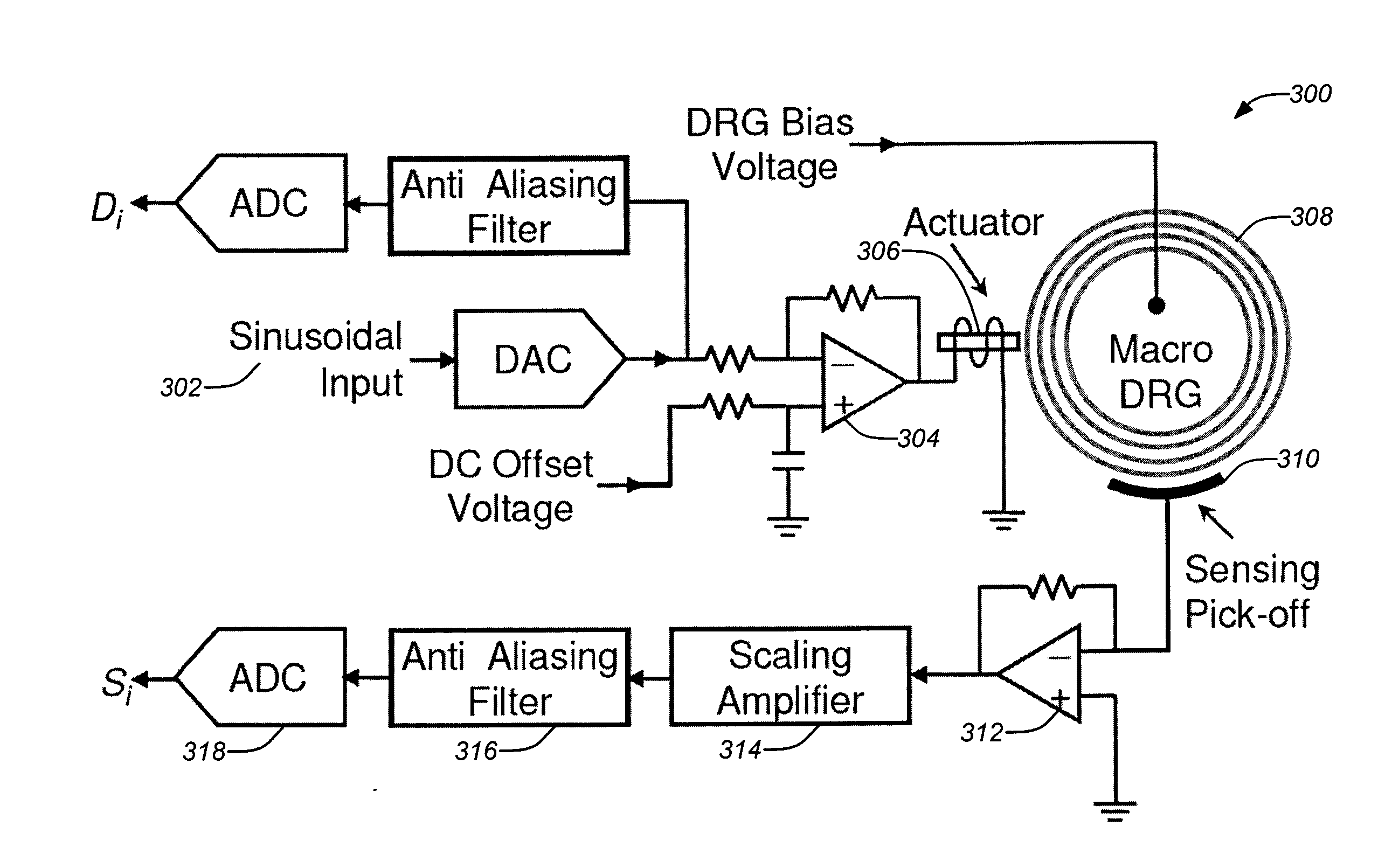
[0044]This disclosure presents techniques for tuning the resonant modes in MEMS vibratory gyroscopes using mass perturbation of the sensor's resonant structure. The approach ameliorates the stringent bias voltage stability requirements and can be applied to any resonator gyroscope that relies on modal frequency matching for optimum performance.

[0045]Tuning modes of a disc resonator gyroscope (e.g., the SiDRG) can be accomplished by using a laser to strategically trim the resonator. I...


PUM


Abstract

Techniques for reducing the frequency split between the Coriolis-coupled modes in disc resonator gyroscopes (DRGs) by perturbing the mass distribution on the disc resonator based on an identified model are disclosed. A model-identification method of tuning a resonator comprises perturbing the mass and measuring a frequency response matrix of the resonator. The frequency response matrix includes a plurality of inputs and a plurality of outputs and the resonator has a plurality of coupled resonance modes. A reduced structural mechanics matrix model of the resonator in sensor and actuator coordinates is identified from the measured frequency response matrix and analyzed to determine generalized eigenvectors of the structural mechanics model and their variations due to selected mass perturbations which is then estimated to improve degeneracy of the plurality of coupled resonance modes based on the generalized eigenvectors of the mass and the stiffness.

Description

CROSS-REFERENCE TO RELATED APPLICATIONS[0001]This application claims the benefit under 35 U.S.C. § 119(e) of the following co-pending U.S. Provisional Patent Application, which is incorporated by reference herein:[0002]U.S. Provisional Application Ser. No. 61 / 060,400, filed Jun. 10, 2008, by Schwartz et al., entitled “FREQUENCY TUNING OF DISC RESONATOR GYRO VIA MASS MATRIX PERTURBATION” (Attorney Docket Number 08-0579).[0003]This application is related to the following co-pending applications, which are all incorporated by reference herein:[0004]U.S. patent application Ser. No. 12 / 473,084, filed May 27, 2009, and entitled “ISOLATED ACTIVE TEMPERATURE REGULATOR FOR VACUUM PACKAGING OF A DISC RESONATOR GYROSCOPE”, by Ge et al. (Attorney Docket Number 08-0830 / BOECP059);[0005]U.S. patent application Ser. No. 12 / 416,911, filed Apr. 1, 2009, and entitled “ENVIRONMENTALLY ROBUST DISC RESONATOR GYROSCOPE”, by Ge et al. (Attorney Docket Number 08-0917 / BOECP058);[0006]U.S. patent application ...

Claims


Application Information

Patent Timeline
Patent Type & Authority Applications(United States)
IPC IPC(8): G01C19/56
CPCG01C19/5684
Inventor SCHWARTZ, DAVID M.KIM, DONG-JOONM'CLOSKEY, ROBERT T.CHALLONER, A. DORIAN
Owner RGT UNIV OF CALIFORNIA
Why Eureka
Try Eureka