Jet Hammer

a technology of hammer and ring spring, which is applied in the direction of portable drilling machines, manufacturing tools, and borehole/well accessories, etc., can solve the problems of stressing of the ring spring assembly, and achieve the effect of less compressibility

Active Publication Date: 2009-12-10
SWINFORD JASON L +1
View PDF24 Cites 32 Cited by
  • Summary
  • Abstract
  • Description
  • Claims
  • Application Information

AI Technical Summary

Benefits of technology

[0016]An exemplary embodiment of the jet hammer includes an outer sleeve, impact assembly, and a valve assembly. The impact assembly is positioned in sliding relation to the outer sleeve to provide the impact of the jet hammer. The impact assembly may also be capable of rotational movement with respect to the outer sleeve. The valve assembly generally comprises a cap screw, adjustment sleeve, valve port, inner compression spring, outer compression spring, and lock nut. The inner compression spring is relatively less compressible than the outer compression spring. In operation, fluid enters

Problems solved by technology

Pulling upward on the jar causes a

Method used


Image

  • Jet Hammer
  • Jet Hammer
  • Jet Hammer

Examples


Embodiment Construction

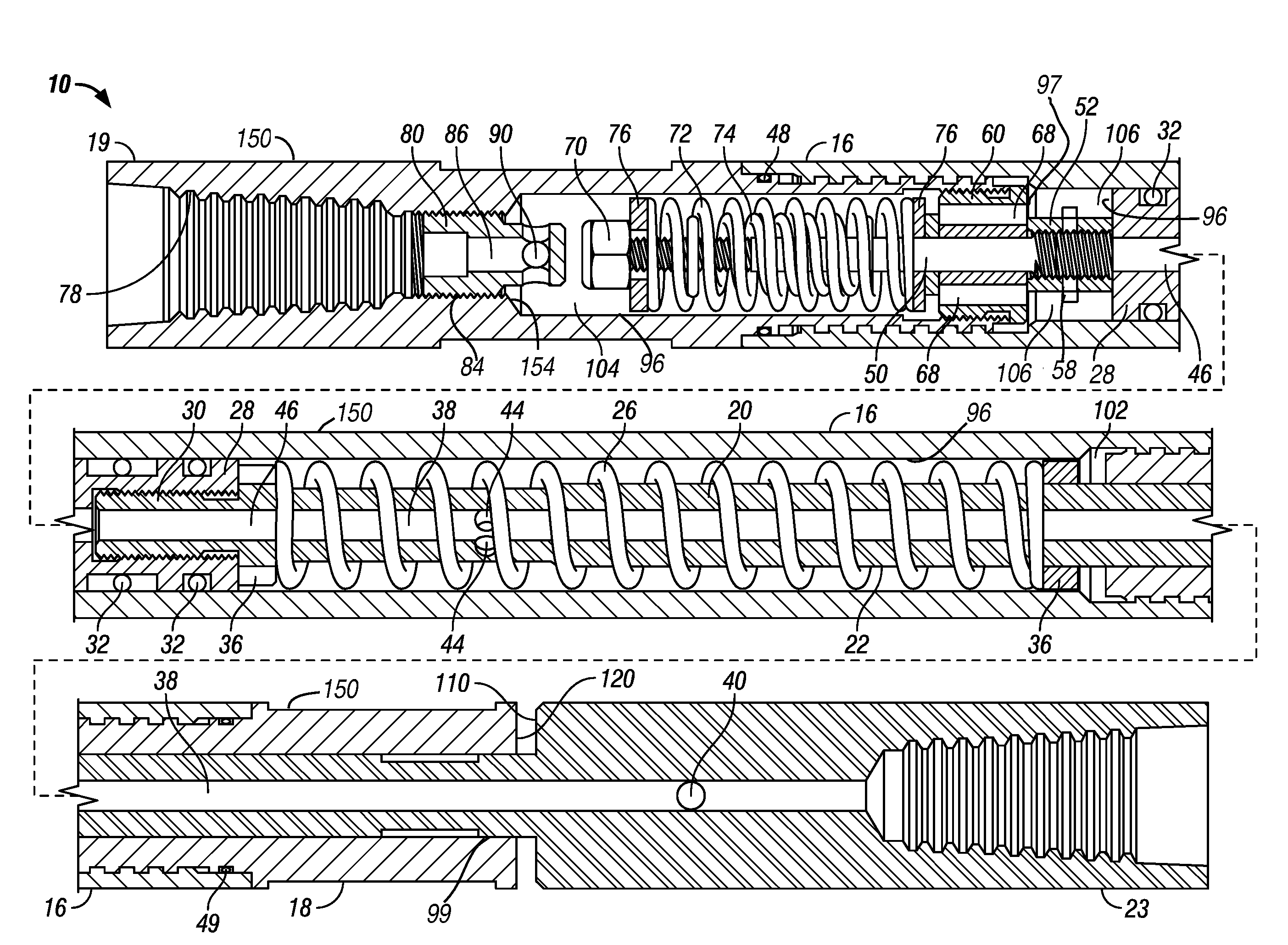
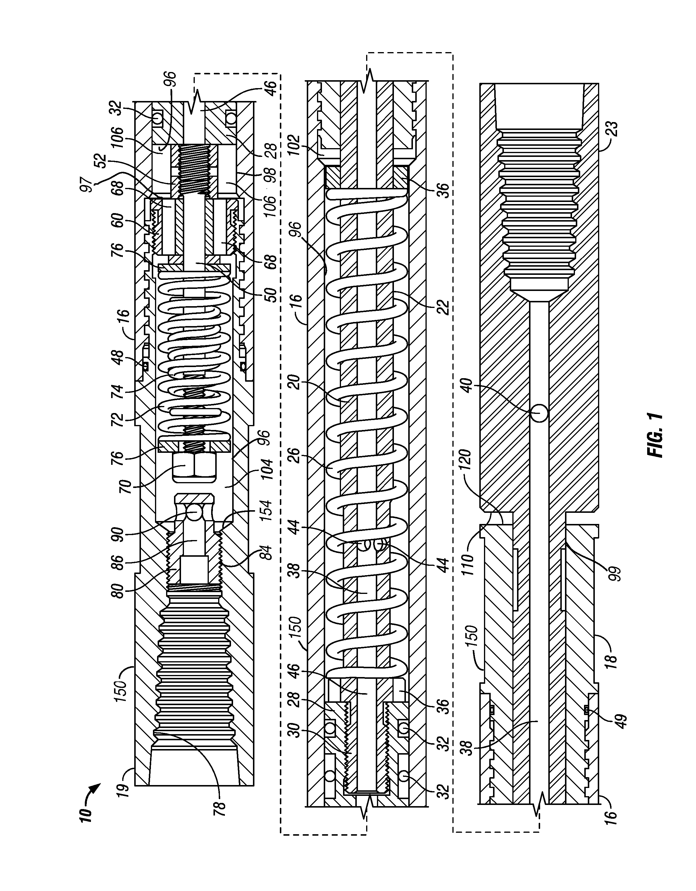
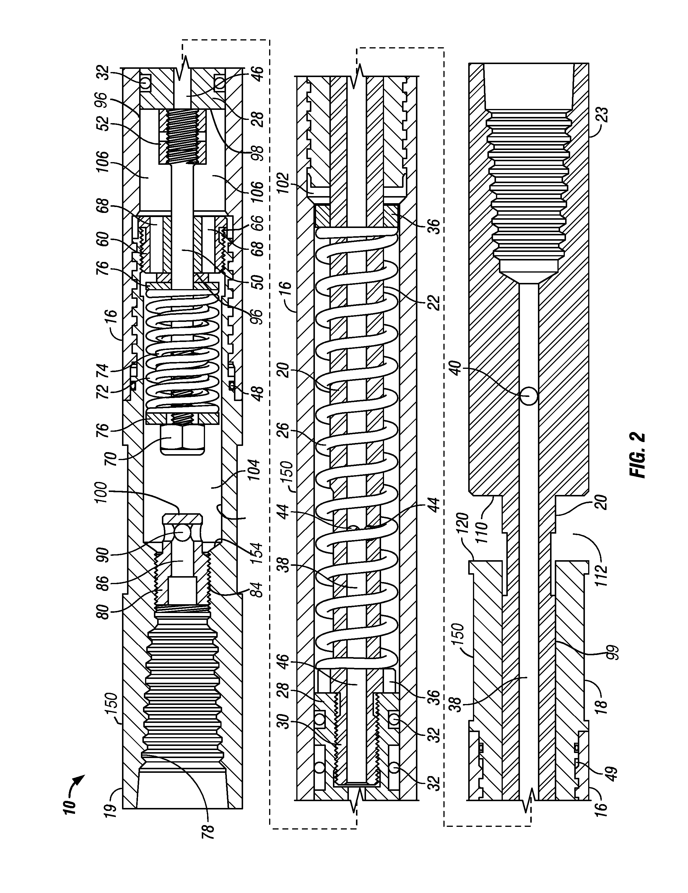
[0036]The described exemplary and alternative embodiments of the invention are best understood by referring to the drawings, like numerals being used for like and corresponding parts of the various drawings. In FIGS. 1, 2, and 3 there is shown, in longitudinal cross-sectional view, an exemplary embodiment of a jet hammer, generally designated 10. The exemplary embodiment of the jet hammer 10 generally includes an upper sub 19, a barrel 16, a valve assembly 14 (see FIG. 6), and an impact assembly 12 (see FIG. 5) all having a common central axis.

[0037]As used herein, “upper” will refer to the direction of the upper sub 19 that connects to a drill string or tubing (not shown). As used herein, “lower” will refer to the direction of the obstruction or structure to be impacted distal the upper sub 19.

[0038]Referring to FIG. 1, the jet hammer 10 contains an outer sleeve 150 that is generally comprised of the upper sub 19, the barrel 16, and the lower sub 18. The upper sub 19 is constructed...


PUM

PropertyMeasurementUnit
Forceaaaaaaaaaa
Pressureaaaaaaaaaa
Compressibilityaaaaaaaaaa

Abstract

An exemplary embodiment of the jet hammer includes an outer sleeve, impact assembly, and a valve assembly. The impact assembly is positioned in sliding relation to the outer sleeve to provide the impact of the jet hammer. The valve assembly generally comprises a cap screw, adjustment sleeve, valve port, inner compression spring, outer compression spring, and lock nut. The inner compression spring is relatively less compressible than the outer compression spring. In operation, fluid enters the valve assembly and acts on the compression springs forming an operational seal between the valve assembly and the impact assembly. In response, the outer sleeve is slidingly displaced from the impact assembly thereby compressing a main compression spring positioned along the mandrel shaft. Once the pressure acting on the valve assembly is released, the main compression spring decompresses forcefully causing the outer sleeve to impact a connection port, bit, tool, or other member attached to the upper end of the mandrel. This impact is translated onto the obstruction or item to be struck. The impact assembly may also be capable of rotational movement with respect to the outer sleeve wherein the mandrel shaft may contain at least one rotation nozzle thereon. The rotation nozzles allow for fluid communication from the mandrel's internal bore, through the nozzles, and against the proximate inner wall of the outer sleeve. This interaction causes the mandrel, and by connection the connection port, bit, tubing, or tool attached thereto, to rotate during the downward stroke of the hammer. Rotation nozzles may be located on the connection port and/or bit for additional rotational force.

Description

CROSS-REFERENCE TO RELATED APPLICATIONS[0001]This application claims the benefit of U.S. provisional application Ser. No. 61 / 059,439 filed on Jun. 6, 2008, which application is incorporated herein by reference as if reproduced in full below.STATEMENT REGARDING FEDERALLY SPONSORED RESEARCH OR DEVELOPMENT[0002]Not applicable.BACKGROUND OF THE INVENTION[0003]1. Field of the Invention[0004]The invention relates generally to impact devices for use during downhole operations. More specifically, the invention is directed to an impact device capable of rotation for use with coiled tubing.[0005]2. Description of the Related Art[0006]The use of mechanical or fluid driven downhole impact tools, hammers, jarring tools, and percussion drilling tools is known in the art, as described in the following U.S. patents.[0007]U.S. Pat. No. 3,612,191 to Martini discloses a fluid operated percussion drilling tool that uses drill bit jet nozzles for hole bore cleaning, as well as for rotary drilling of pet...

Claims


Application Information

Patent Timeline
IPC IPC(8): E21B1/38
CPCE21B4/14E21B41/0078E21B6/06
Inventor SWINFORD, JERRY L.
Owner SWINFORD JASON L
Why Eureka
Try Eureka