Method of Controlling the Tension of a Bin Carousel Chain

a carousel chain and tension control technology, applied in the direction of conveyors, materials strength using tensile/compressive forces, instruments, etc., can solve the problems of chain not being inspected frequently enough, non-negligible accident risk for the operator, and damage to the bins, etc., to achieve convenient adjustment

Inactive Publication Date: 2009-12-10
SOLYSTIC
View PDF10 Cites 9 Cited by
  • Summary
  • Abstract
  • Description
  • Claims
  • Application Information

AI Technical Summary

Benefits of technology

[0027]In the method of the invention, a contactless sensor is used to detect the undulations going past in the slack run, e.g. an inductive sensor, an optical sensor, or the like so that monitoring the tension of a bin carrousel drive chain is independent of the length of the chain. For the inductive sensor, it is possible to use the sensor called “IFFM 20P17A3” sold by “Baumer”, that sensor being quite compact so that it is easy to accommodate in the cramped spaces of a bin carrousel.

Problems solved by technology

It is therefore necessary to check frequently the tension of the chains since an over-tensioned chain might be damaged under forces that are too large, and an under-tensioned chain might give rise to the bins being damaged by them hitting one another.
In addition, since the inspection must be performed while the machine is operating, there exists a non-negligible risk of accident for the operator, who has to lean into the casing of the machine to come close enough to the chains while said chains are moving.
Finally, the chains are not inspected frequently enough to mitigate any risk of a chain breaking, due, for example, to the chain becoming rapidly over-tensioned.
Such checking is impossible on a drive chain of a bin carrousel of a postal sorting machine due to the presence of the bins coupled to the chain.
Such an installation is very complex and costly to implement.
That method is not suitable for the length of a drive chain of a bin carrousel of a postal sorting machine.

Method used


Image

  • Method of Controlling the Tension of a Bin Carousel Chain
  • Method of Controlling the Tension of a Bin Carousel Chain
  • Method of Controlling the Tension of a Bin Carousel Chain

Examples


Embodiment Construction

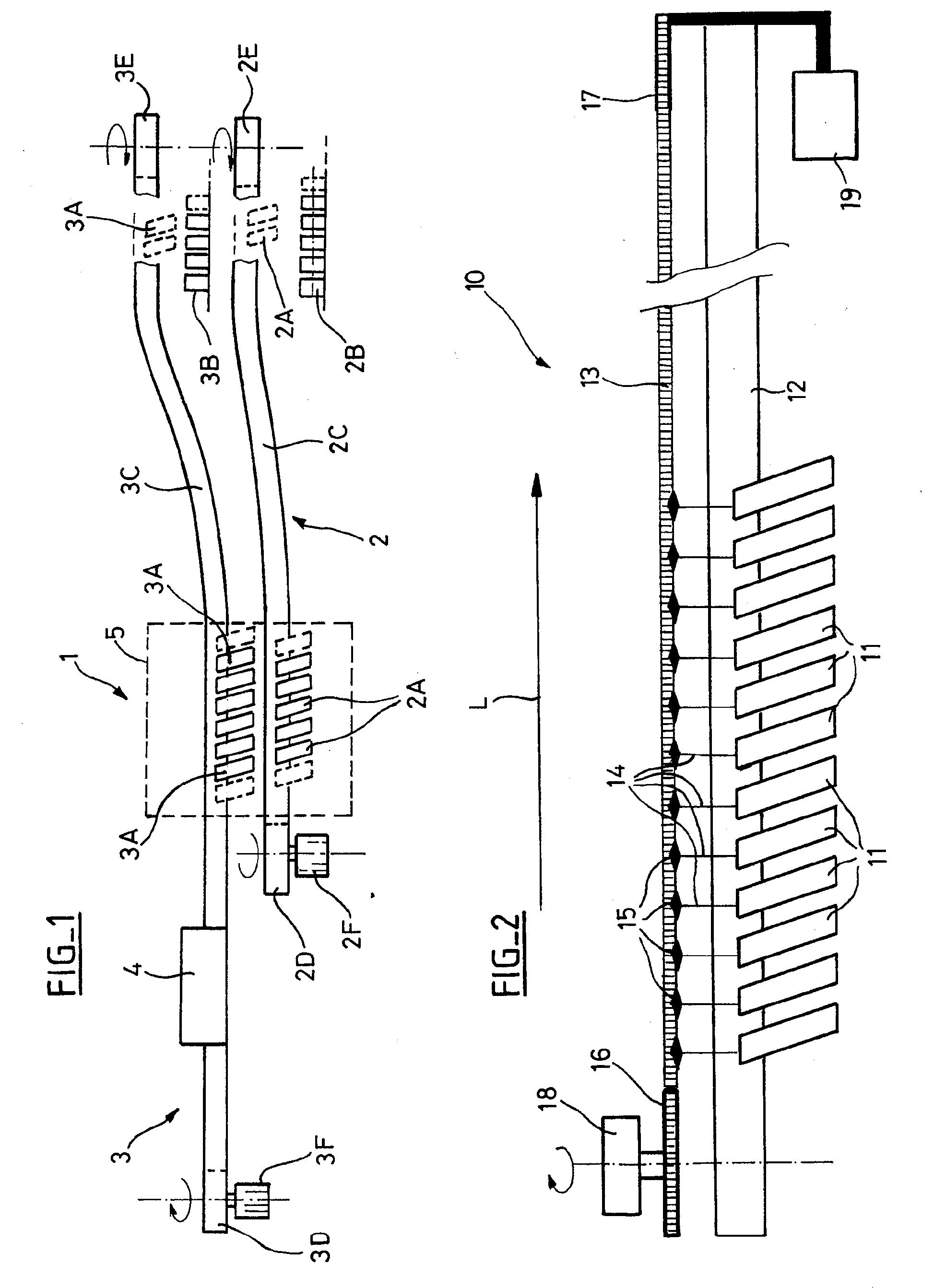
[0041]The method of the invention can be implemented in a mail handling machine that is analogous to the mail handling machine shown in FIG. 1 and described in Patent Document EP 1 222 036 and applies more particularly to devices having a closed-loop chain driven to be moved at a single point.

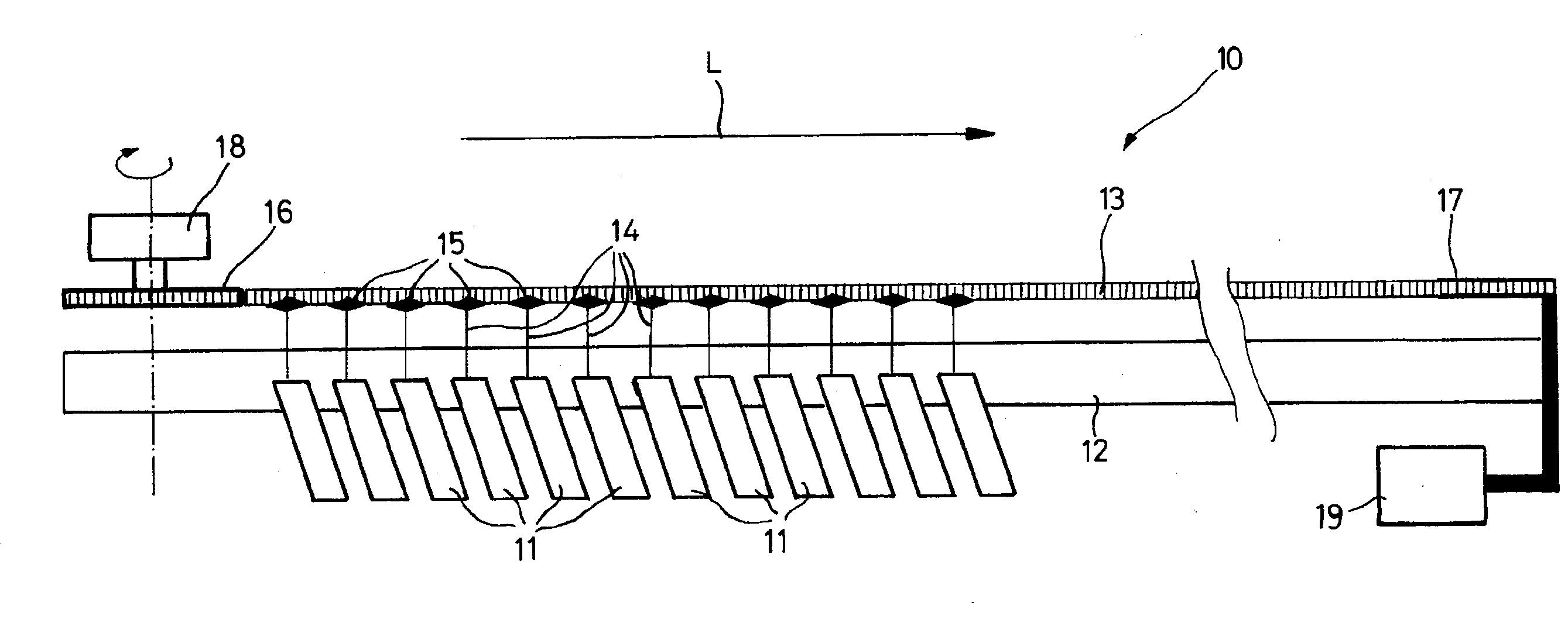
[0042]In order to simplify the description of the invention, a single bin carrousel of a mail handling (postal sorting) machine is shown in FIG. 2. The carrousel 10 comprises bins 11 for conveying postal items.

[0043]The bins 11 move around a path forming a closed loop. Each of the bins 11 has a roller bearing and guide system that is mounted to move in a system of rails 12 in the direction L. The roller system is drivingly coupled, so that it moves in direction L, to an endless chain 13, e.g. a roller chain, via a hanger arm 14 and via a fastening caliper 15 represented by a diamond-shape in FIG. 2. In practice, the bins 11 of the carrousel are distributed at a uniform distance apart over the e...


PUM

PropertyMeasurementUnit
lengthaaaaaaaaaa
widthaaaaaaaaaa
widthaaaaaaaaaa

Abstract

A method of monitoring the tension of a continuous endless drive elongate member (13) mounted to be moved over a closed-loop path and having a slack run along which it forms undulations, said method consisting in placing a sensor (23) along said slack run for detecting undulations going past in the slack run, and in counting the number of undulations detected, said number serving as a magnitude for measuring the tension of the drive member.

Description

CROSS REFERENCE TO RELATED APPLICATIONS[0001]This application is a 35 U.S.C. §371 National Phase Application from PCT / FR2007 / 051575, filed Jul. 2, 2007, and designating the United States, which claims the benefit of France Patent Application No. 0653271, filed Aug. 3, 2006.BACKGROUND OF THE INVENTION[0002]1. Field of the Invention[0003]The invention relates to a method of monitoring the tension of a continuous endless drive elongate member mounted to be moved over a closed-loop path and having a slack run along which it forms undulations.[0004]The invention applies more particularly to a mail handling machine having one or more bin carrousels whose bins are driven to move around a closed-loop path via a drive chain, e.g. an endless roller chain, or indeed a cable or a belt.[0005]2. Discussion of the Background Art[0006]Such a mail handling machine that more particularly has two superposed bin carrousels is known, for example, from European Patent Document EP 1 222 036 and is shown i...

Claims


Application Information

Patent Timeline
Patent Type & Authority Applications(United States)
IPC IPC(8): B65G17/36B65G43/00B65G17/00G01L5/04
CPCB65G43/00B65G23/44
Inventor MARISY, STEPHANELEOPOLD, BRUNODECHARRAN, DOMINIQUEDANJAUME, ALAIN
Owner SOLYSTIC
Why Eureka
Try Eureka