
Reduced-complexity multiple-input, multiple-output detection

a detection and multi-output technology, applied in the field of communication systems, can solve the problems of sacrificing reliability of mimo demapping, affecting the accuracy of data detection, so as to reduce the set of computations

Inactive Publication Date: 2009-12-10
AVAGO TECH INT SALES PTE LTD
View PDF10 Cites 93 Cited by
  • Summary
  • Abstract
  • Description
  • Claims
  • Application Information

AI Technical Summary

Benefits of technology

This approach enhances the reliability of signal detection, reduces circuit complexity and power consumption, and maintains rapid computation while improving the probability of detection in MIMO systems.

Problems solved by technology

Therefore, typical single-antenna demodulation (e.g., soft-slicing) techniques are not applicable, and MIMO demodulators (“demappers”) are employed instead.
Due to the random mutual cross-talk of transmit streams in the wireless MIMO channel, MIMO demapping can exhibit irregular performance.
Prior art MIMO demappers either sacrifice reliability or are relatively complex to implement.
While the approach of these MIMO demappers is relatively simple to implement, suppression of mutual cross-talk between the separated signal streams might lead to noise-enhancement.
In noise-enhancement, the effective Signal-to-Noise Ratio (SNR) in the various reconstructed signal streams might be relatively low depending on the properties of the wireless channel, leading to significant degradation in the generation of soft bits.
However, the complexity of the search process is typically prohibitive for high-data-rate systems.
While the number of candidate metrics may be reduced by, for example, spherically constrained decoding, a very complex process might be required in practice to identify the relevant candidates.
Moreover, when the number of candidate metrics is reduced, ensuring that the true candidate is actually found is difficult.
Another disadvantage is that the spherically constrained search is performed separately per soft bit.

Method used


Image

  • Reduced-complexity multiple-input, multiple-output detection
  • Reduced-complexity multiple-input, multiple-output detection
  • Reduced-complexity multiple-input, multiple-output detection

Examples


Embodiment Construction

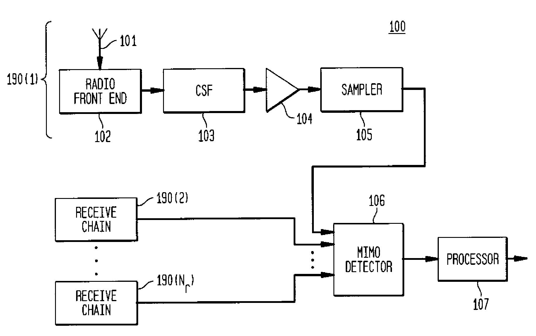
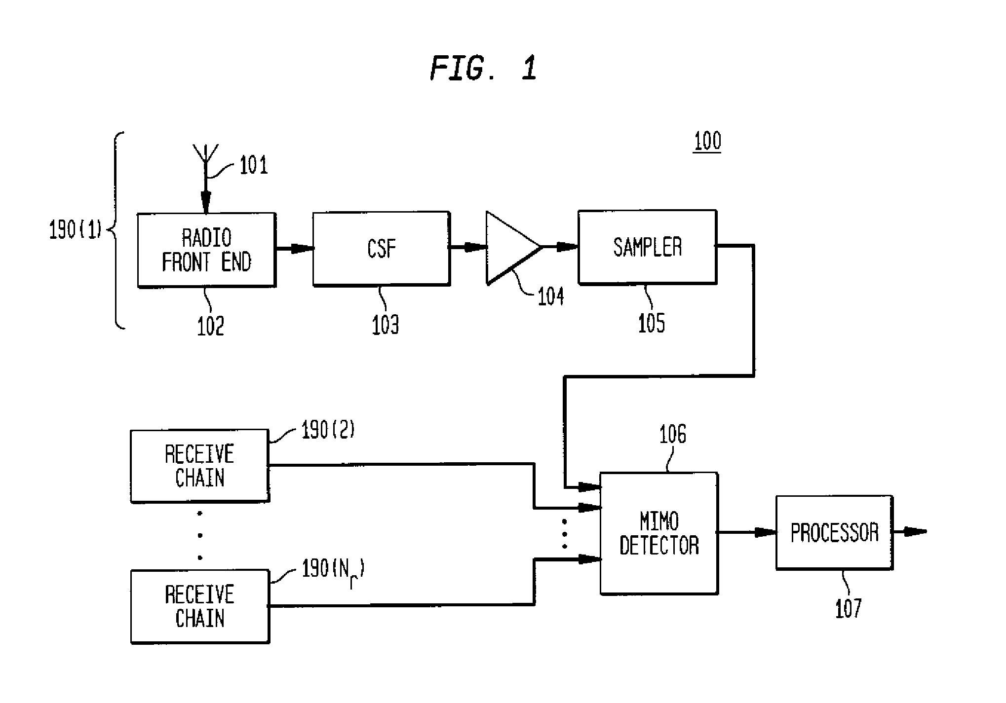
[0024]FIG. 1 shows a multiple-input, multiple-output (MIMO) receiver 100 operating in accordance with exemplary embodiments of the present invention. Receiver 100 comprises Nr receive chains 190(1) through 190(Nr), where Nr is a positive. Typically, a MIMO receiver comprises two or more receive chains, where each receive chain might operate in a similar manner.

[0025]Receive chain 190(1) comprises antenna 101, radio front end (RFE) 102, channel selection filter (CSF) 103, programmable gain amplifier (PGA) 104, and sampler 105. Antenna 101 detects a signal from, for example, a wireless communication channel, where the signal might comprise two or more antenna signals generated by a MIMO transmitter. RFE 102 receives the signal from antenna 101, band filters and gain adjusts the antenna signal, and demodulates the antenna signal to base-band (BB) or near-BB.

[0026]CSF 103 filters the signal from RFE 102 so as to pass the desired information channel. For example, CSF 103 might be configu...


PUM


Abstract

A wireless receiver detects signals generated with a multiple-input, multiple-output (MIMO) transmitter. The receiver applies maximum-likelihood detection (MLD) for soft-output signal detection, where an MLD exhaustive search across all candidate vectors is performed recursively by computing and accumulating the differences between, for example, the Euclidean metrics of consecutive candidate tests. Difference terms used for the accumulation are also calculated recursively. An ordering of candidates, such as by a triangular-waveform shaped ordering, is employed such that only one candidate variable is changed between any two consecutive candidate evaluations, leading to a reduced set of computations.

Description

CROSS-REFERENCE TO RELATED APPLICATION[0001]This is a continuation of co-pending application Ser. No. 10 / 990,910, filed on Nov. 17, 2004 as attorney docket no. Graef 1-5, the teachings of which are incorporated herein by reference.BACKGROUND OF THE INVENTION[0002]1. Field of the Invention[0003]The present invention relates to communication systems, and, in particular, to data detection employing a multiple-input, multiple-output demapper.[0004]2. Description of the Related Art[0005]Reliable and efficient transmission of information signals over imperfect communication channels is essential for wireless communication systems. One method of transmission is multiple-input, multiple-output (MIMO) transmission. For MIMO transmission, a transmitter sends separate signals on two or more transmit antennas, the separately transmitted signals are combined as they pass through the channel, and the receiver receives the combined signals on each of one or more receive antennas. The receiver dete...

Claims


Application Information

Patent Timeline
Patent Type & Authority Applications(United States)
IPC IPC(8): H04L27/06
CPCH04B7/0413H04L5/0023H04L25/0204H04L25/0224H04L25/03191H04L2025/03643H04L25/03318H04L27/2647H04L2025/03414H04L2025/03426H04L25/0321
Inventor GRAEF, NILSHAMMERSCHMIDT, JOACHIM S.
Owner AVAGO TECH INT SALES PTE LTD
Learn More