
Motor-driven scroll type compressor

a compressor and motor technology, applied in the direction of machines/engines, rotary/oscillating piston pump components, liquid fuel engines, etc., can solve the problems of deteriorating the durability of bearings, failure of back pressure chambers to function, and failure of compression units in compressing refrigerant gas

Active Publication Date: 2009-12-10
TOYOTA IND CORP
View PDF8 Cites 25 Cited by
  • Summary
  • Abstract
  • Description
  • Claims
  • Application Information

AI Technical Summary

Problems solved by technology

However, the reduction of the oil rate of the refrigerant gas flowing out to the external refrigerant circuit decreases the supply of lubricating oil to the bearing that is located far from the compression unit thereby to deteriorate the durability of the bearing.
If the invention of this Publication having no throttle in the oil supply passage is applied to a motor-driven scroll type compressor having the back pressure chamber, the pressure in the back pressure chamber leaks excessively through the oil supply passage due to the absence of the throttle in the oil supply passage, with the result that the back pressure chamber fails to function to urge the movable scroll member toward the fixed scroll member.
This will result in failure of the compression unit in compressing refrigerant gas.
While it may be conceivable to provide a throttle in the oil supply passage so as to make effective the function of the back pressure chamber, it is actually difficult to form a throttle in the oil supply passage in the rotary shaft.

Method used


Image

  • Motor-driven scroll type compressor
  • Motor-driven scroll type compressor
  • Motor-driven scroll type compressor

Examples


first embodiment

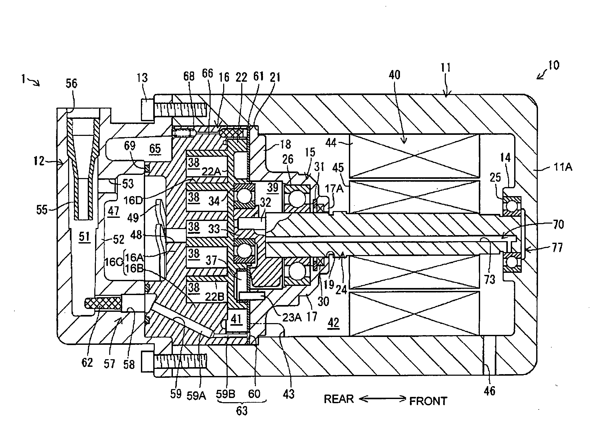
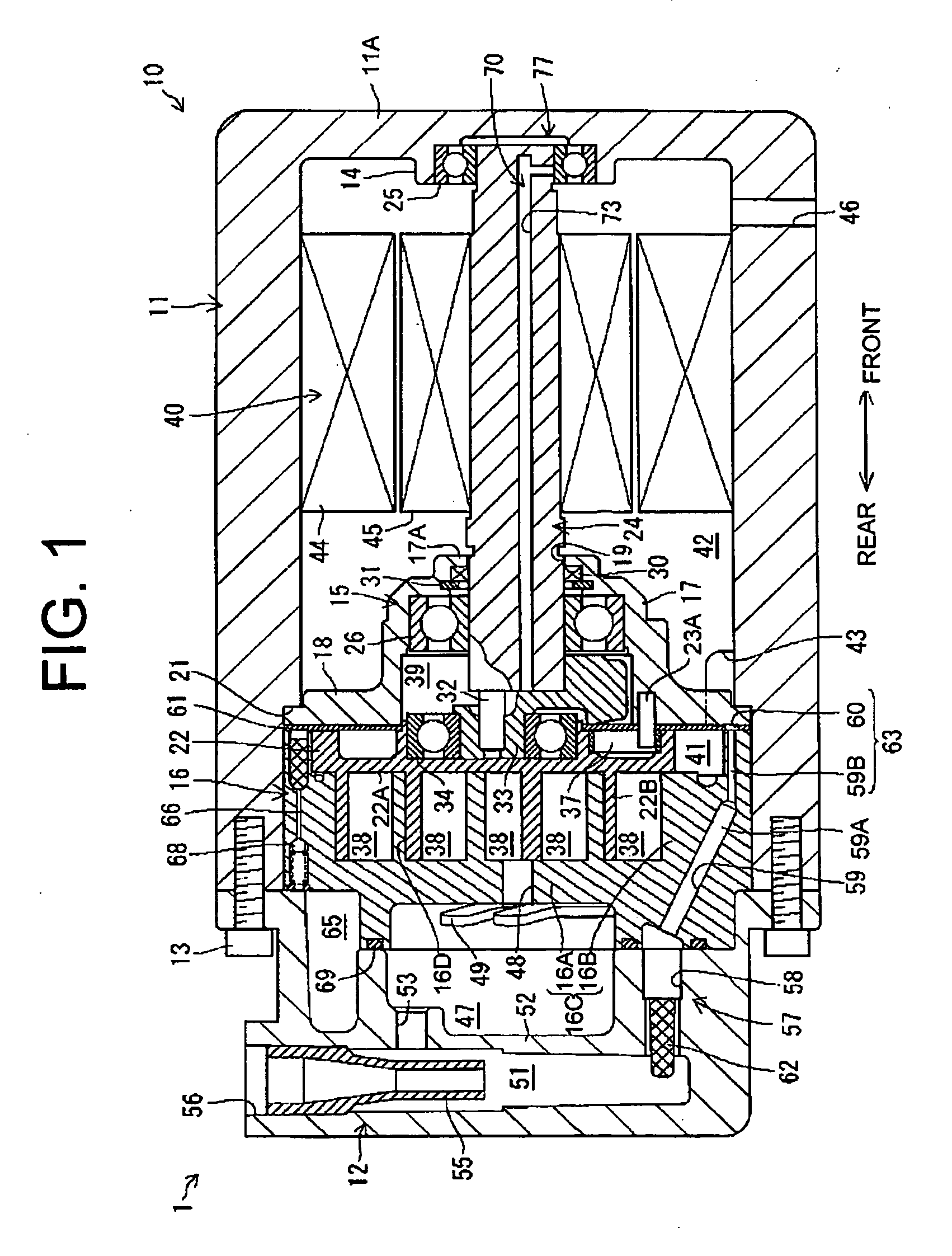
[0019]A motor-driven scroll type compressor 1 of the first embodiment has a housing 10, as shown in FIG. 1. The housing 10 includes a cylindrical front housing 11 with a bottom, a cover-like rear housing 12 and a shaft support member 15. The shaft support member 15 is provided in the front housing 11 and a fixed scroll member 16 is provided behind the shaft support member 15. The rear end of the front housing 11 and the front end of the rear housing 12 are jointed and fastened together by bolts 13 and the front housing 11 and the rear housing 12 cooperate to accommodate therein the fixed scroll member 16 and the shaft support member 15 in contact with each other.

[0020]The front housing 11 has a cylindrical boss 14 protruding from the center of bottom wall 11A of the front housing 11. The shaft support member 15 has a cylindrical portion 17 and a flange portion 18 extending outward from the rear end of the cylindrical portion 17. The bottom wall 17A of the cylindrical portion 17 has ...

second embodiment

[0044]In the motor-driven scroll type compressor 1 according to the second embodiment shown in FIG. 5, the first opening 71 is opened somewhere in the range between 0° and 90° in the orbital direction R of the movable scroll member 22 from an imaginary reference line SL that extends from the zero point 0 corresponding to the central axis O of the rotary shaft 24 and passes through the central axis Q of the eccentric pin 32. The rest of the structure of the compressor is substantially the same as that of the first embodiment.

[0045]According to the inventors, the outer peripheral surface 24C at the front end portion 24A of the rotary shaft 24 approaches closest to the inner surface 28C of the inner ring 28 of the bearing 24 in the above range.

[0046]At what degree with respect to the line “SL” the outer peripheral surface 24C approaches most close to the inner surface 28C varies depending on the compression reactive force and other factors. Therefore, forming the first opening 71 withi...


PUM


Abstract

A motor-driven scroll type compressor has a motor that includes a rotary shaft and rotates the rotary shaft, a bearing for rotatably supporting front end of the rotary shaft, a fixed scroll member, a movable scroll member driven by rear end of the rotary shaft, compression chambers defined by the movable scroll member and the fixed scroll member and a housing. The rotation of the rotary shaft makes an orbital motion of the movable scroll member around the axis of the rotary shaft and accordingly the compression chambers are moved radially and inwardly thereby to compress the refrigerant gas. The compressor further has a suction chamber communicating with the compression chambers, a discharge chamber, an oil separation chamber separating lubricating oil from the refrigerant gas and communicating with the discharge chamber and a back pressure chamber provided in front of the movable scroll member in the housing and facing to the rear end of the rotary shaft. The back pressure chamber communicates with the oil separation chamber. The rotary shaft includes a first opening at a position adjacent to the front end of the rotary shaft and facing an inner surface of the bearing, a second opening at a position adjacent to the rear end of the rotary shaft and communicating with the back pressure chamber, a communication passage interconnecting the first opening and the second opening and a throttle formed by a clearance between the first opening and the inner surface of the bearing.

Description

BACKGROUND OF THE INVENTION[0001]The present invention relates to a motor-driven scroll type compressor.[0002]A motor-driven scroll type compressor having a motor for driving a rotary shaft of the compressor and a scroll type compression unit for compressing refrigerant gas is generally known. In this motor-driven scroll type compressor, the motor serves as a drive source and the scroll type compression unit serves as a scroll type compressor. The motor-driven scroll type compressor has bearings provided on opposite ends of the rotary shaft with the motor located therebetween for reducing the load on the rotary shaft.[0003]It is also known that the performance of the refrigeration system can be improved by separating lubricating oil e.g. by an oil separator from the compressed high-temperature and high-pressure refrigerant gas flowing out from the compression unit to an external refrigerant circuit for reduction of the oil rate.[0004]However, the reduction of the oil rate of the ref...

Claims


Application Information

Patent Timeline
IPC IPC(8): F04C29/02F04C18/02
CPCF04C18/0215F04C23/008F04C2240/807F04C29/026Y10S418/01F04C29/023
Inventor KII, NORIMICHISUITOU, KENITO, TATSUYA
Owner TOYOTA IND CORP
Features
  • Generate Ideas
  • Intellectual Property
  • Life Sciences
  • Materials
  • Tech Scout
  • Unparalleled Data Quality
  • Higher Quality Content
  • 60% Fewer Hallucinations
Learn More