Contact Spring in a Support Frame of an Antenna Amplifier of a Vehicle

a technology of contact springs and support frames, which is applied in the direction of electrically conductive connections, antenna connectors, coupling devices, etc., can solve the problems of inability to achieve specific and targeted design, and achieve the effect of reducing contact force, reducing abrasive wear around the contact surface, and specificity

Active Publication Date: 2009-12-10
HIRSCHMANN CAR COMMUNICATION
View PDF4 Cites 4 Cited by
  • Summary
  • Abstract
  • Description
  • Claims
  • Application Information

AI Technical Summary

Benefits of technology

[0009]In a complementary or alternative embodiment of the invention as indicated in claim 2, provision is made whereby the number of blades turned toward the one contact surface and / or their width is different from the number of blades and / or their width turned toward the other contact surface. This provides the advantage that different contact forces can be applied since based on their dimensions and / or materials different contact surfaces require different contact forces, which can be optimally adjusted by means of the number of blades and / or their width. In particular, the use of narrower blades enables the contact force to be reduced, and thus the abrasive wear around the contact surface also to be reduced. At the same time, e.g. given narrower blades, the requisite spring forces can be provided by the higher number of blades. If, however, the spring force should be equal on both sides of the spring-type contact, the combined width of all blades on each side of the spring-type contact can be the same. This means that given a different width and different number of blades on the one and the other side, the spring force or spring travel is nevertheless equal. If, however, different spring forces and / or spring travels are required, this can also be provided by the design of the blades according to the invention. If, however, the contact force should be equal on both sides of the spring-type contact, the total number of blades on each side of the spring-type contact can also be same. All of this can be adjusted in a specific and targeted manner in the spring-type contact according to the invention since this spring is anchored only at one end and has a free end, with the result that a specific, and most importantly, known length compensation is possible here. With a spring-type contact that is anchored at both ends, this specific and targeted design would not be possible.

Problems solved by technology

With a spring-type contact that is anchored at both ends, this specific and targeted design would not be possible.

Method used


Image

  • Contact Spring in a Support Frame of an Antenna Amplifier of a Vehicle
  • Contact Spring in a Support Frame of an Antenna Amplifier of a Vehicle
  • Contact Spring in a Support Frame of an Antenna Amplifier of a Vehicle

Examples


Embodiment Construction

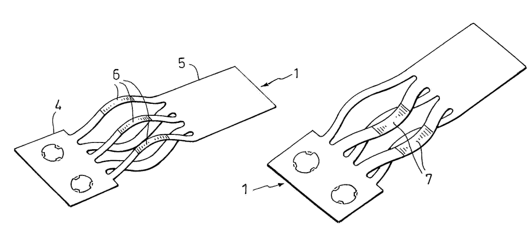
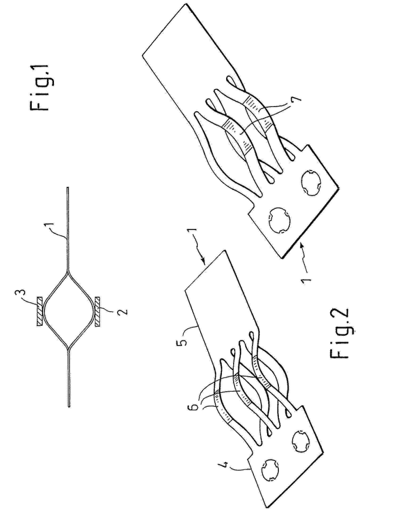
[0018]FIG. 1 shows, to the extent details are illustrated, the basic configuration of a spring-type contact 1 of blade design between two contact surfaces 2 and 3, where e.g. contact surface 2 is on a face of a printed-circuit board of an antenna amplifier while contact surface 3 is mounted on a face of a two-dimensional component of a vehicle having an antenna conductor structure. A basic design of this type in terms of the constructive details, as shown in FIG. 1, is known from EP 1 080 513.

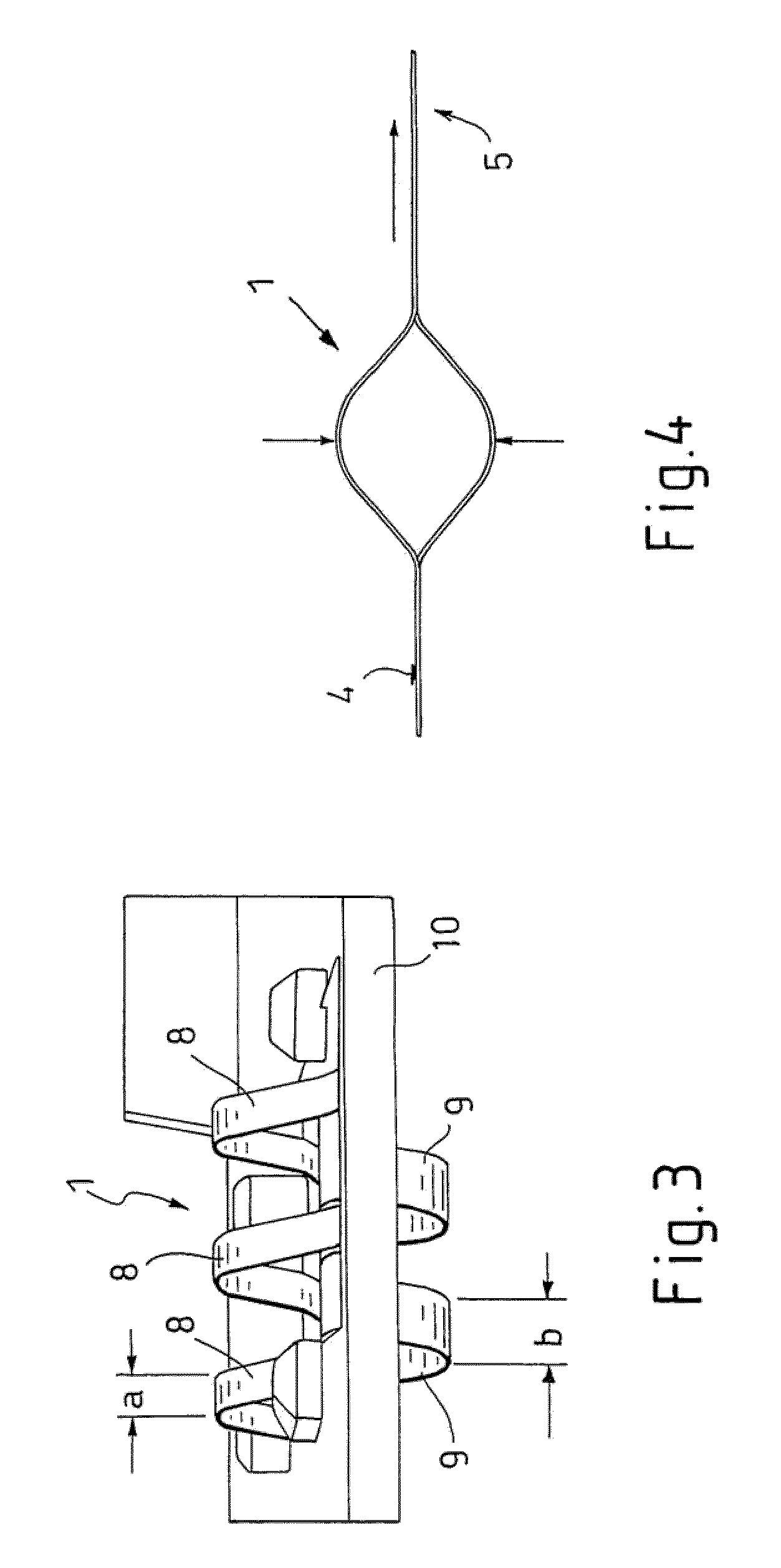
[0019]FIG. 2 shows that spring-type contact 1 is composed of a base material having spring properties and has an anchored end 4 as well as a freely movable end 5. A blade connection, one side turned toward the contact surface 2 and the other side turned toward the contact surface 3, is provided between these two ends 4 and 5. This design shape shown in FIG. 2 for spring-type contact 1 can be produced by a simple stamping process. FIG. 2 also shows that the bowed top and bottom regions, where th...


PUM


Abstract

The invention relates to a contact spring (1) which has lamellae (8, 9) in the direction of a respective contact area (2, 3), it being possible to bring the lamellae (8, 9) into contact with the contact areas (2, 3) by means of contact points (6, 7), wherein the invention provides that at least one of the contact points (6, 7) has a coating, with the respective material of the coating being matched to the material of the contact area (2, 3).

Description

TECHNICAL FIELD[0001]The invention relates to a spring-type contact as according to the introductory clause of claims 1 or 2.PRIOR ART[0002]A spring-type contact that has blades each turned toward a respective contact surfaces, the blades having contact points movable into contact with the contact surfaces, is described in EP 1 523 069 [U.S. Pat. No. 7,121,835]. The spring-type contact described and illustrated therein has an anchored end by which the spring-type contact can be anchored in or onto a support frame. One free end remote from the anchored end can move in a recess of the support frame in one direction, this movement being critical when the spring-type contact is brought and thereby compressed between the two contact surfaces. Practice has shown that the design of this type of spring-type contact with upwardly and downwardly projecting blades is quite advantageous since damage from the closed blades can be prevented, and even extreme compression of the blades does not res...

Claims


Application Information

Patent Timeline
Patent Type & Authority Applications(United States)
IPC IPC(8): H01R4/48
CPCH01R4/4881H01R2201/02H01R13/03H01R4/62
Inventor SILVA, DAVIDHAUSSLER, HELMUT
Owner HIRSCHMANN CAR COMMUNICATION
Why Eureka
Try Eureka