Opaque corneal insert for refractive correction

a corneal insert and insert technology, applied in the field of opaque corneal insert for refractive correction, can solve the problems of eyeglasses and contact lenses having to be cleaned and periodically replaced, eyeglasses may be especially cumbersome to carry, and the error of refraction in the visual process

Inactive Publication Date: 2009-12-10
ACUFOCUS
View PDF100 Cites 55 Cited by
  • Summary
  • Abstract
  • Description
  • Claims
  • Application Information

AI Technical Summary

Benefits of technology

[0021]In some embodiments, the outer periphery of the opaque member defines a first dimension and an inner edge of an iris of the eye defines a second dimension when the pupil is dilated (either fully or partially dilated). The first dimension is equal to or less than the second dimension. At least a portion of the outer periphery can be positioned within the optical zone of the eye.

Problems solved by technology

Deviations from the proper shape of the corneal produce errors of refraction in the visual process.
Unfortunately, eyeglasses and contact lenses have to be cleaned and periodically replaced.
Eyeglasses may be especially cumbersome to carry and may be cosmetically unappealing.
Contact lenses have to be replaced frequently and, consequently, can be quite expensive.
These procedures are relatively complex and are often irreversible.
Unfortunately, these rings may have relatively large dimensions (e.g., inner diameters, outer diameters, and thicknesses).
If placed close to the optical zone, these rings could cause optical distortions.
These rings can have long healing times, in part due to their size, and may result in scar tissue build up, thus reducing the efficacy of the implanted rings.

Method used


Image

  • Opaque corneal insert for refractive correction
  • Opaque corneal insert for refractive correction
  • Opaque corneal insert for refractive correction

Examples


Embodiment Construction

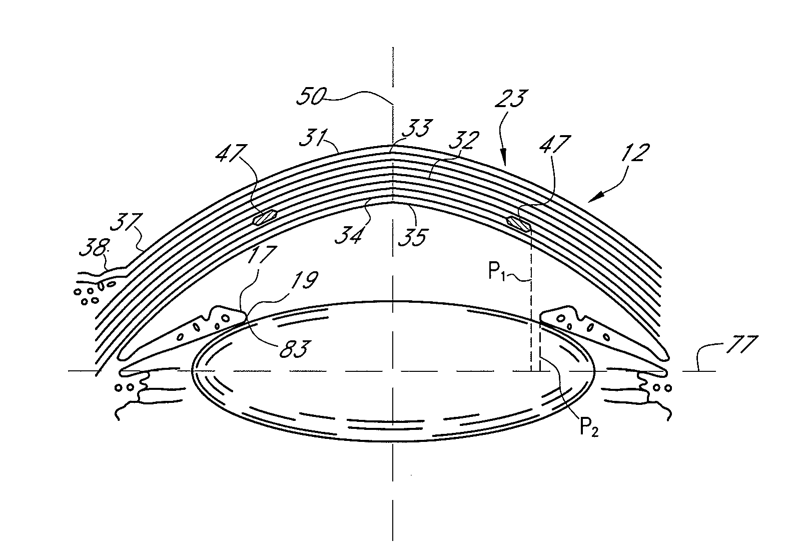
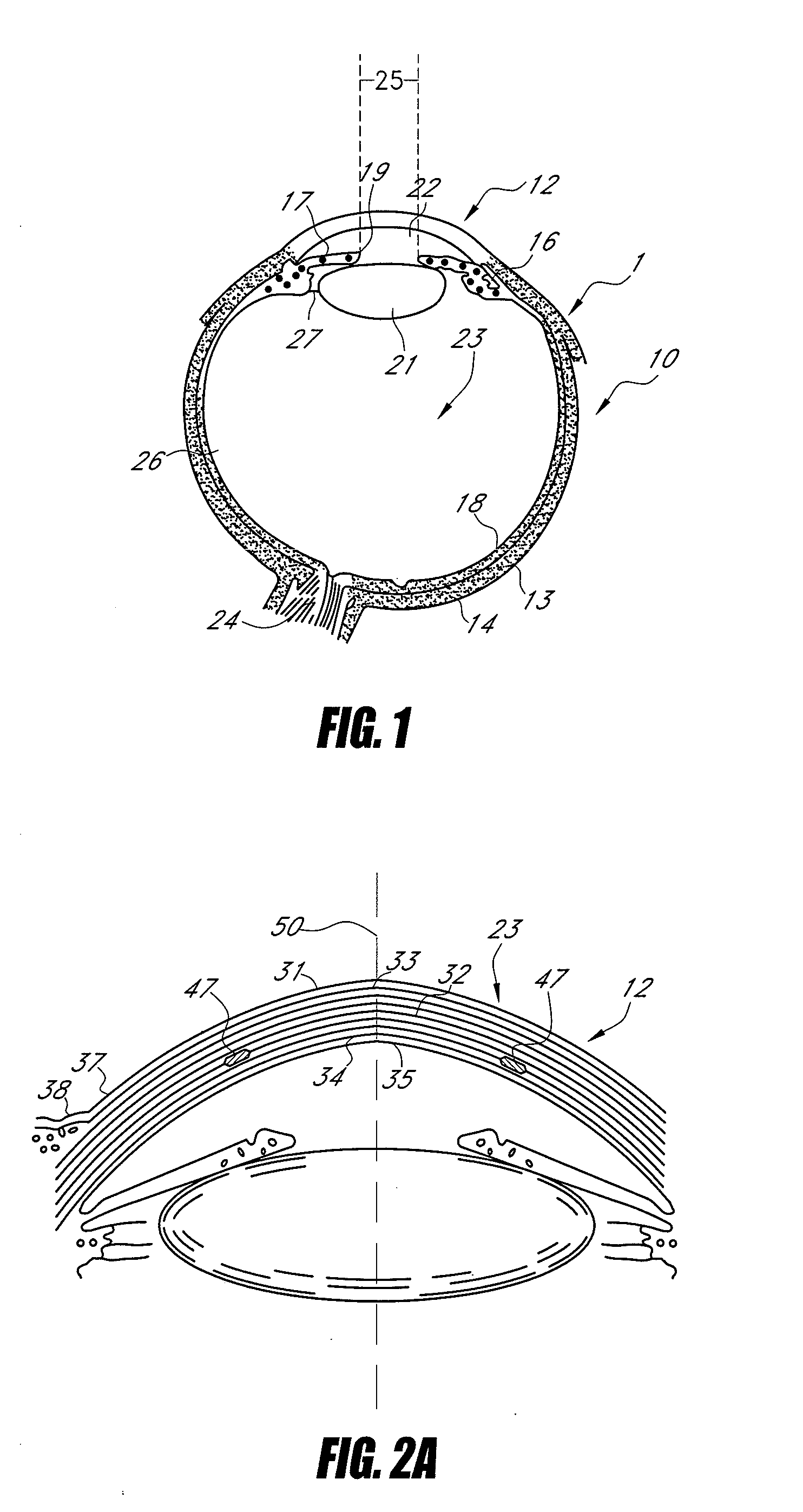
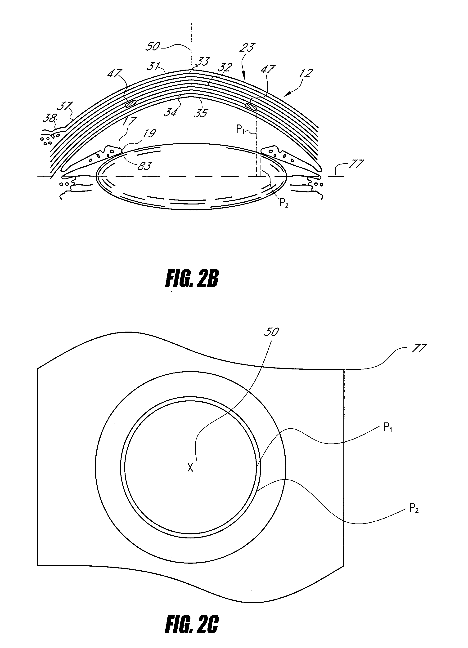
[0045]FIG. 1 shows a horizontal section of an eye 1, which has a generally spherical portion, referred to herein as an eyeball 10. The eye 1 includes a cornea 12, which is an anterior bulged spherical portion of the eye 1, and a sclera 13 enclosing the transparent media through which the light passes to reach the retina 18. The retina 18 includes light sensitive tissue and is located at the back of the eye 1. The sclera 13 is a fibrous protective portion and constitutes approximately the posterior ⅚ of the eyeball 10. The sclera 13 is white and opaque and the visible portion of the sclera is sometimes referred to as the “white” of the eye. The anterior ⅙ of the eyeball 10 is the cornea 12.

[0046]An interior covering or layer of the eye 1 is vascular and nutritive in function and includes the choroid 14, the ciliary body 16, and the iris 17. This interior covering maintains the retina 18. The ciliary body 16 supports a lens 21 and is involved in accommodation. The iris 17 is the most ...


PUM


Abstract

Implants configured for corneal implantation are disclosed that have a light transmitting portion and a light-blocking portion disposed about the periphery of the implant. The implant can be an elongate member, such as a split or continuous ring, that can be implanted in the cornea to alter the refractive properties of the cornea by altering the curvature of the anterior surface of the cornea, thereby providing corrective refraction. The light-blocking portion can reduce edge effects, which may be visible or distracting to the patient.

Description

BACKGROUND OF THE INVENTION[0001]1. Field of the Invention[0002]This invention relates to methods and apparatuses for modifying the shape of portions of an eye, for example changing curvature of the cornea of the eye.[0003]2. Description of the Related Art[0004]Deviations from the proper shape of the corneal produce errors of refraction in the visual process. The properly shaped eye in a state of rest, without accommodation, focuses the image of distant objects exactly on the retina. Such an eye enjoys distinct vision for distant objects without effort. Any variation from this standard constitutes ametropia, a condition in which the eye at rest is unable to focus the image of a distant object on the retina. Hyperopia (“farsightedness”) is an error of refraction in which, with the eye at rest, parallel rays from distant objects are brought to focus behind the retina. Divergent rays from near objects are focused still further back.[0005]The corneal surface of a hyperopic eye is often ...

Claims


Application Information

Patent Timeline
Patent Type & Authority Applications(United States)
IPC IPC(8): A61F2/14A61B19/00
CPCA61F2250/0053A61F2/147
Inventor SILVERSRINI, THOMASCHRISTIE, BRUCE A.
Owner ACUFOCUS
Why Eureka
Try Eureka