System and method of detecting air pollution, route-planning method applied to said detection system, and warning method of air pollution

a detection system and air pollution technology, applied in the field of detection systems and methods applied in the field of systems for detecting air pollution and methods applied thereto, can solve the problems of air pollution having a direct negative effect on the health of human bodies, plants and animals, and more and more chemical components exhausted into the air

Inactive Publication Date: 2009-12-17
NAT TAIWAN UNIV
View PDF26 Cites 64 Cited by
  • Summary
  • Abstract
  • Description
  • Claims
  • Application Information

AI Technical Summary

Benefits of technology

[0016]Compared with the prior art, the air pollution detection system and method of the present invention overcome drawbacks of conventional fixed air pollution detecting devices, and the air pollution detection system of present invention is capable of transmitting detected data and real-time position data back to a control center via the network system by means of a movable detection device and a communication transmission device, and thus enabling the control center to obtain air pollution data of a wider a

Problems solved by technology

However, there are more and more chemical components exhausted into the air because of industry development and internal combustion engines widely adopted by various transportation devices; and it is very common to have a hazardous chemical component above a safety level.
Once a hazardous chemical component is above safety level, air pollution will happen.
Air pollution has a direct negative effect on the health of human bodies, plants, and animals.
Indirectly, air pollution causes acid rain and global warming.
However, technique of the established devices has the following drawbacks:(1) area under detection is not wide enough; due to restriction of the established technique or insufficient budge, the air pollution detecting device is commonly installed at a fixed location, thereby incapable of detecting air pollution occuring at other places; even though a

Method used


Image

  • System and method of detecting air pollution, route-planning method applied to said detection system, and warning method of air pollution
  • System and method of detecting air pollution, route-planning method applied to said detection system, and warning method of air pollution
  • System and method of detecting air pollution, route-planning method applied to said detection system, and warning method of air pollution

Examples


Embodiment Construction

[0025]The following illustrative embodiments are provided to illustrate the disclosure of the present invention, these and other advantages and effects can be apparently understood by those in the art after reading the disclosure of this specification. The present invention can also be performed or applied by other different embodiments. The details of the specification may be on the basis of different points and applications, and numerous modifications and variations can be devised without departing from the spirit of the present invention.

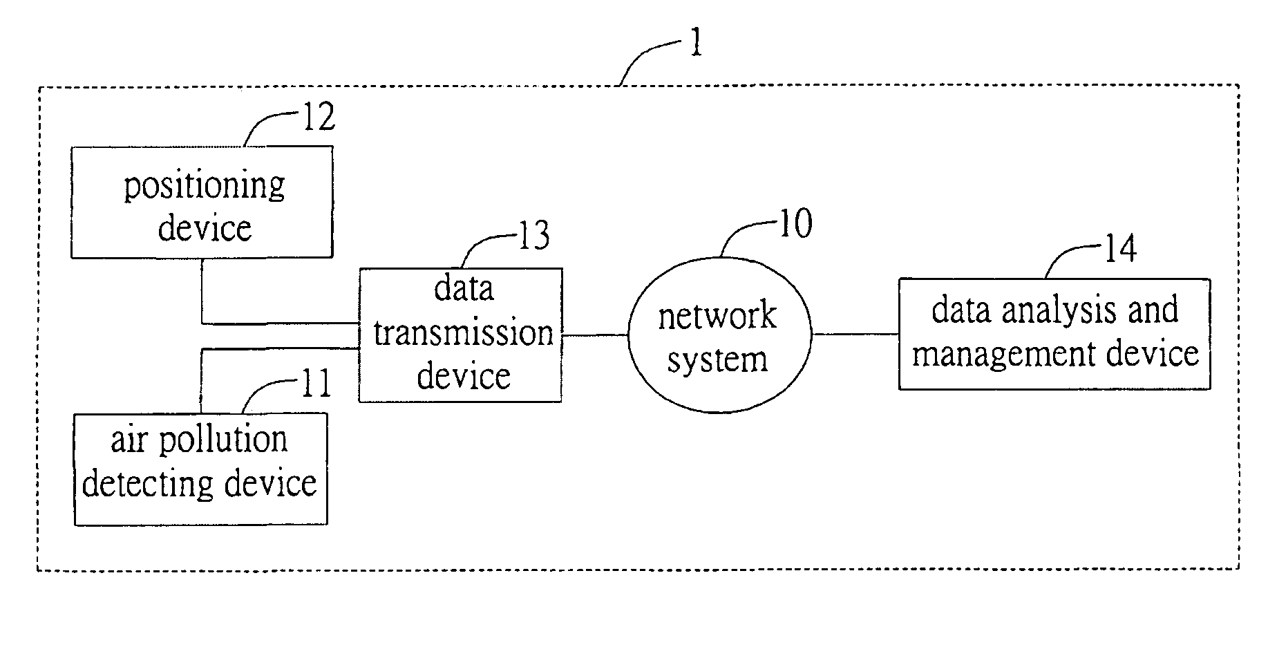
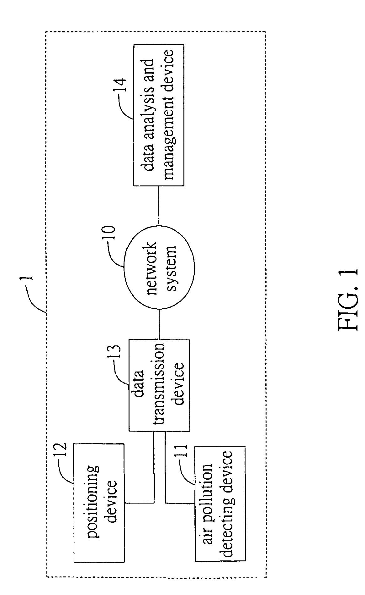
[0026]Please refer to FIG. 1, which is an architecture diagram of air pollution detection system of the present invention; as shown in the FIG., the present invention is applicable to a network system 10, and the air pollution detection system 1 comprises air pollution detecting device 11, positioning device 12, data transmission device 13, and data analysis and management device.

[0027]The network system 10, which performs as a data transmission ...


PUM


Abstract

Provided are a system and method for detecting air pollution, characterized by using an air pollution detecting device for detecting air pollutants, using a positioning device for locating the air pollution detecting device, and enabling a data transmission device to transmit air pollution data and position data to a data analysis and management device via a network system, and then enabling the data analysis and management device to perform analysis and management process on the data; accordingly, perceiving air pollution status at each area and thus proving air pollution information and improvement to air pollution areas in a shorter time.

Description

BACKGROUND OF THE INVENTION[0001]1. Field of the Invention[0002]This invention generally relates to a system for detecting air pollution and a method applied thereto, and more specifically, to a movable real-time air pollution detection system and a method applied thereto.[0003]2. Description of Related Art[0004]There are various kinds of chemical particles in the air we breathe every day. Given endurable concentration, the chemical particles generally have no direct ecological influence on our daily life. However, there are more and more chemical components exhausted into the air because of industry development and internal combustion engines widely adopted by various transportation devices; and it is very common to have a hazardous chemical component above a safety level. Once a hazardous chemical component is above safety level, air pollution will happen.[0005]There are many sources of air pollution, including: power plants, vehicles, industry plants, etc. Generally speaking, a p...

Claims


Application Information

Patent Timeline
IPC IPC(8): G08B17/10G06F19/00G01W1/02
CPCG01C21/3461G01W1/00G08B27/006G08B27/005G08B21/12
Inventor FU, HUAI-LEIHU, KAI-HSIANGWANG, TING-YULIN, ZIH-CILIN, PHONEFANG, YUGUANG
Owner NAT TAIWAN UNIV
Why Eureka
Try Eureka