Recording apparatus and electronic apparatus

a recording apparatus and electronic technology, applied in the direction of electrical apparatus, printing, pictoral communication, etc., can solve the problems of apparatus receiving an impact force, long waiting time for users, and time-consuming to find the home position of the carriage in the serial printer of the aforementioned typ

Inactive Publication Date: 2009-12-17
SEIKO EPSON CORP
View PDF0 Cites 15 Cited by
  • Summary
  • Abstract
  • Description
  • Claims
  • Application Information

AI Technical Summary

Benefits of technology

[0019]According to the second aspect, since the control unit of the electronic apparatus supplies power to the movement detecting unit, which is configured to detect movement of the drive section, and monitors an amount of movement of the drive section during the power-saving mode, the control unit can ascertain the present state (such as the position or the orientation) of the drive section without having to perform a resetting operation or a home-position seeking operation for ascertaining the position of the drive section after cancelling the power-saving mode. Thus, when an operation execution command is received during the power-saving mode, the operation can be commenced immediately.

Problems solved by technology

However, seeking the home position of the carriage in the serial printer of the aforementioned type is time-consuming.
This undesirably results in a long waiting time for the user.
If the drive section is moved by an external force during the power-saving mode, there is a possibility that the apparatus may have received an impact force.
In that case, if the recording head is an inkjet recording head, air bubbles may possibly form within the nozzles and ultimately result in missing dots.

Method used


Image

  • Recording apparatus and electronic apparatus
  • Recording apparatus and electronic apparatus
  • Recording apparatus and electronic apparatus

Examples


Embodiment Construction

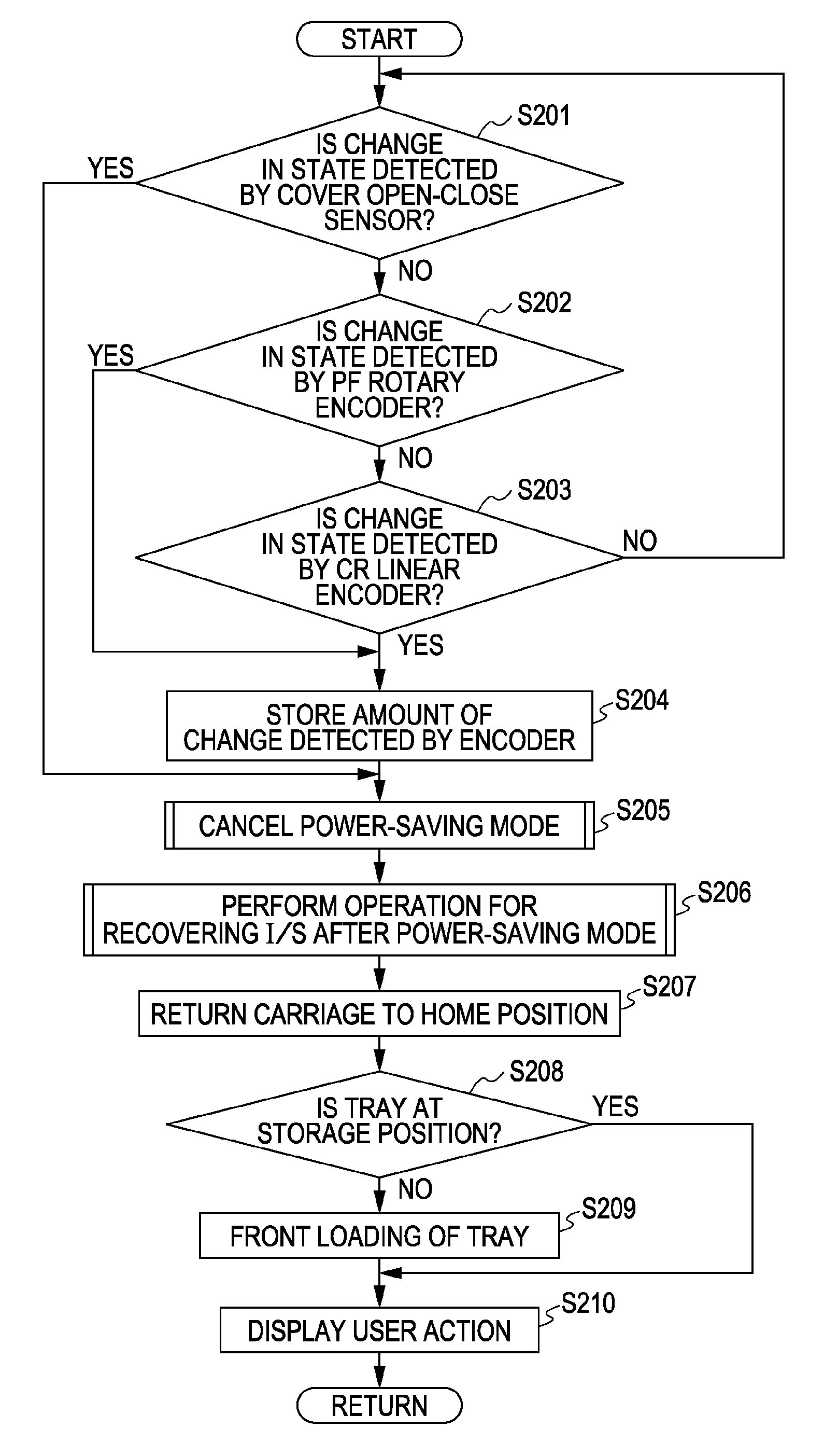
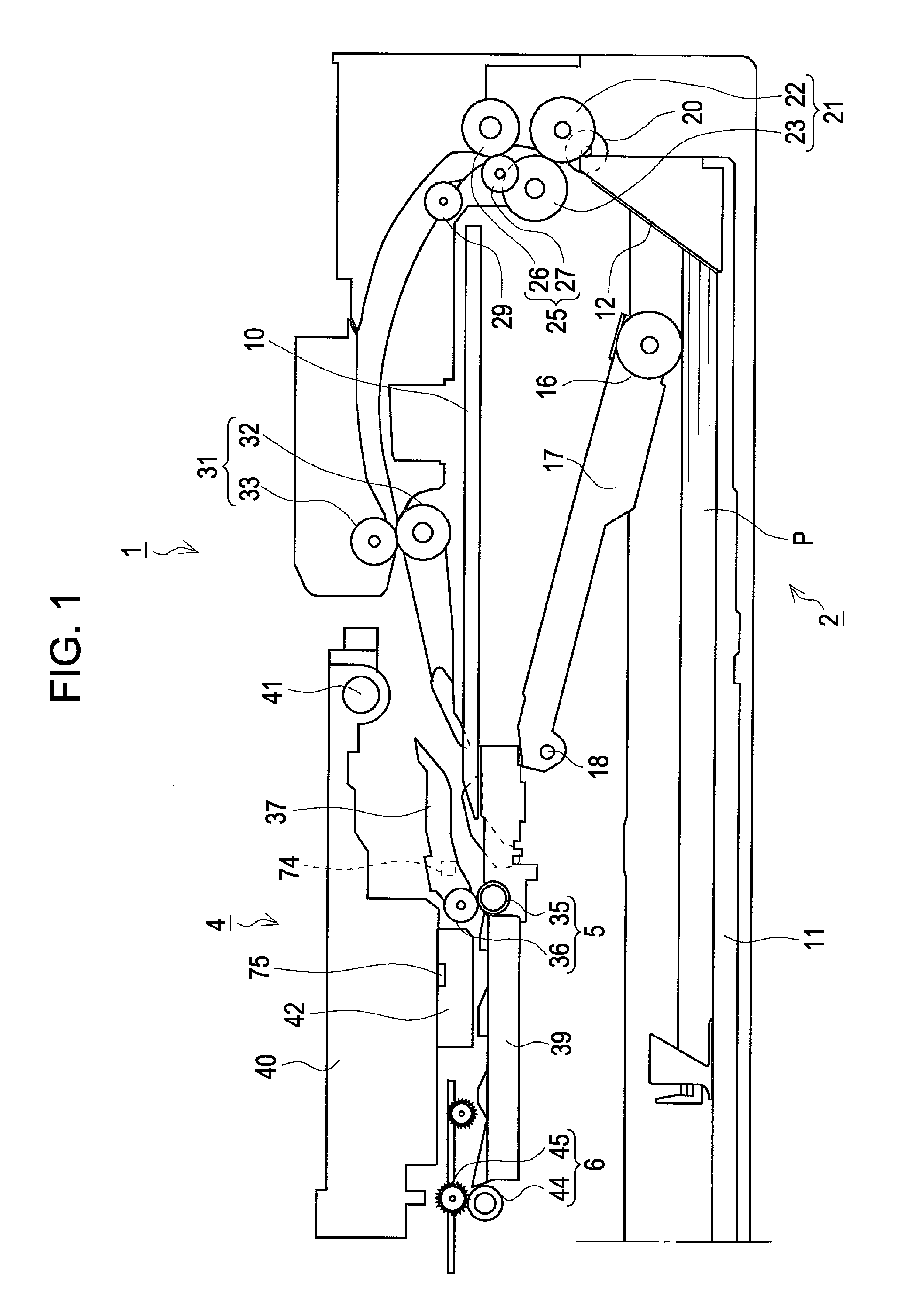
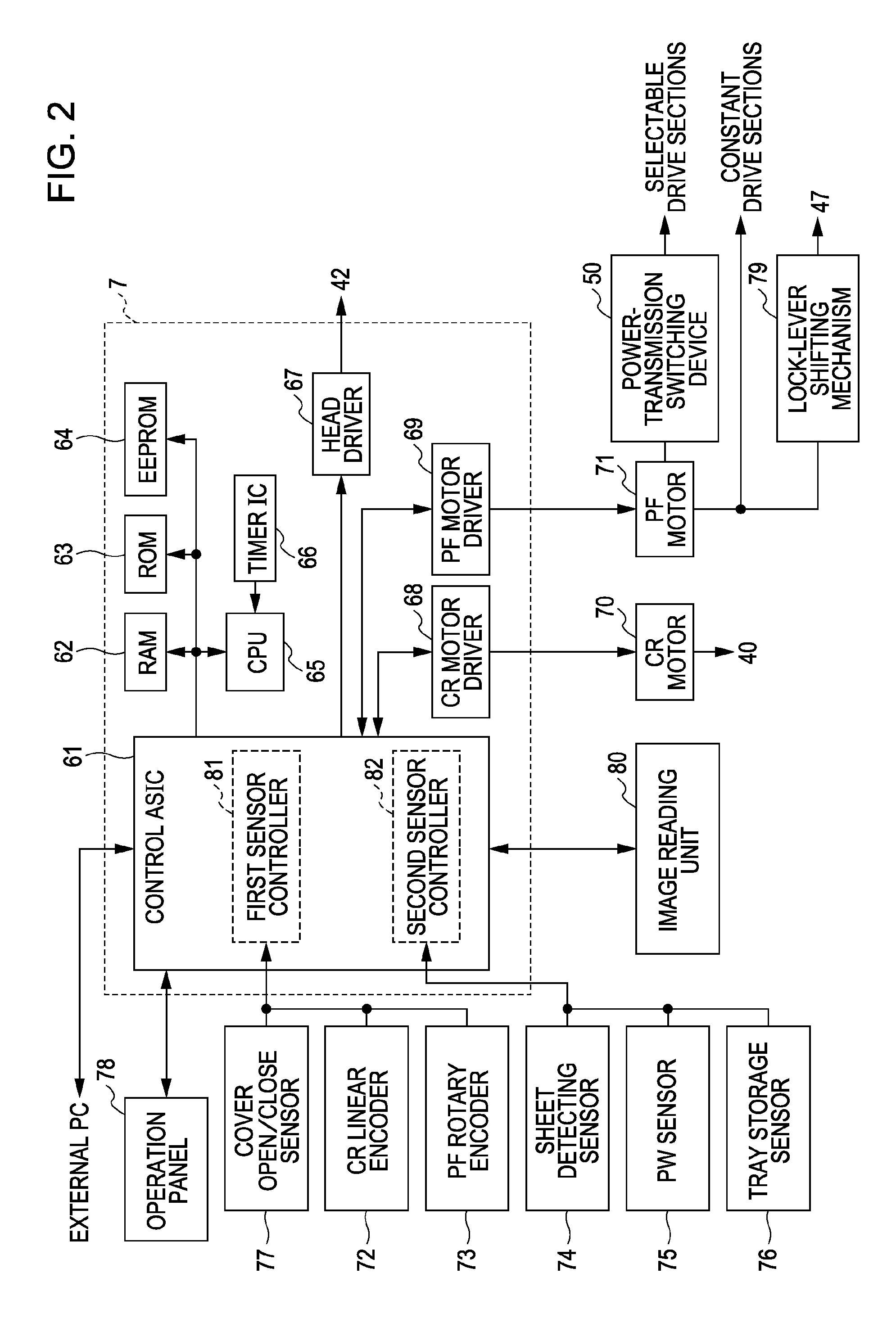
[0026]An embodiment of the invention will now be described with reference to FIGS. 1 to 5. FIG. 1 is a cross-sectional view showing a sheet transporting path in an inkjet printer (referred to as a “printer” hereinafter) 1 as one of examples of a recording apparatus, which is an example of an electronic apparatus according to an embodiment of the invention. FIG. 2 is a block diagram of a control system having a control device 7 as a central unit. FIG. 3 schematically illustrates a movable range of a carriage 40. FIG. 4 is a flow chart illustrating a process for switching to a power-saving mode. FIG. 5 is a flow chart illustrating a process for cancelling the power-saving mode.

[0027]A configuration of the printer 1 will be described below with reference to FIGS. 1 to 3. The printer 1 includes a feeder device 2 at the bottom of the printer 1. The printer 1 is a serial printer that feeds recording sheets P one by one from the feeder device 2, performs inkjet recording on each sheet P at...


PUM


Abstract

A recording apparatus that performs recording on a recording medium includes a control unit. The control unit supplies power to a movement detecting unit, which is configured to detect movement of at least one drive section to be controlled, and monitors an amount of movement of the at least one drive section during a power-saving mode.

Description

BACKGROUND[0001]1. Technical Field[0002]The present invention relates to recording apparatuses typified by facsimile apparatuses and printers, and to electronic apparatuses.[0003]2. Related Art[0004]Recording apparatuses typified by facsimile apparatuses and printers are generally made to switch to a power-saving mode if no operation is performed for a certain period of time while the power is turned on or if there is no input of information from the outside for a certain period of time. Examples of such technology related to a power-saving mode are disclosed in JP-A-2005-238557, JP-A-2005-250326, JP-A-2007-168295, JP-A-2006-201868, and JP-A-2004-357023.[0005]Specifically, JP-A-2005-238557 discloses a serial printer configured to discontinue the supply of power to a carriage-position detecting sensor when switching to a power-saving mode and to seek the home position of the carriage after cancelling the power-saving mode.[0006]JP-A-2005-250326 discloses an image forming apparatus co...

Claims


Application Information

Patent Timeline
Patent Type & Authority Applications(United States)
IPC IPC(8): B41J2/01
CPCH04N1/00885H04N1/00888H04N1/00891H04N2201/0082H04N1/12H04N1/128H04N1/0097
Inventor SHIBASAKI, YOSHIAKINAKAMURA, KAZUHISANOBUTA, KOSAKU
Owner SEIKO EPSON CORP
Why Eureka
Try Eureka