Shading device

a technology of a shield and a shielding pin, which is applied in the direction of door/window shielding devices, mechanical devices, transportation and packaging, etc., can solve the problems of poor efficiency, difficult to visually confirm the small holes of the thin holding pin, and difficulty in operation

Active Publication Date: 2016-09-27
HAYASHI TELEMPU CO LTD +1
View PDF15 Cites 10 Cited by
  • Summary
  • Abstract
  • Description
  • Claims
  • Application Information

AI Technical Summary

Benefits of technology

[0021]Before the shading device is assembled with the body, if the shaft portion is preliminarily wound in the winding direction in a state that the locking member is located at the lock release position and then the locking member is slid to the lock position, the shaft portion can be maintained in a state of being preliminarily wound. After the shading device is assembled, if the operating portion is operated so that the operating portion is flexed, the slide engagement portion is released from the lock position engagement portion. Therefore, the locking member can be easily slid to the lock release position to release the locked state of the shaft portion. Furthermore, even after the locked state of the shaft portion is released once, the rotation of the shaft portion can be prohibited again by sliding the locking member to the lock position. Therefore, if the locking member is slid to the lock position in a state that the shaft portion is preliminarily wound in the winding direction by sliding the locking member to the lock release position again, the shaft portion can be maintained in a state of being preliminarily wound. Thus, an operation inspection of the shading device can be performed many times. In addition, workability during the service operation is improved, for example, when a failure occurs.

Problems solved by technology

If the preliminary winding is performed when the sunshade device is attached, efficiency is not good.
However, it is difficult to visually confirm small holes to which the thin holding pin is inserted.
Therefore, operation becomes difficult and man-hours are increased.
Furthermore, once the winding shaft is unrotatably fixed, inspection work, such as an operation check of opening / closing of the screen, cannot be performed before the sunshade device is assembled on the vehicle.
In addition, when the sunshade device is required to be removed from the vehicle door at the time of providing a service such as the time of repairing the sunshade device, for example, the sunshade device cannot be removed in a state of maintaining the initial torque, i.e., a state of maintaining the state of being preliminarily wound.
Therefore, maintainability is not good.
Therefore, once the tubular body is unrotatably fixed, inspection work of the sunshade device cannot be performed before the sunshade device is assembled on the vehicle also in the above structure.
Note that the above described problems also occur in the shading devices other than the sunshade device, for example, a tonneau cover device.

Method used


Image

  • Shading device
  • Shading device
  • Shading device

Examples


first example

(2) First Example

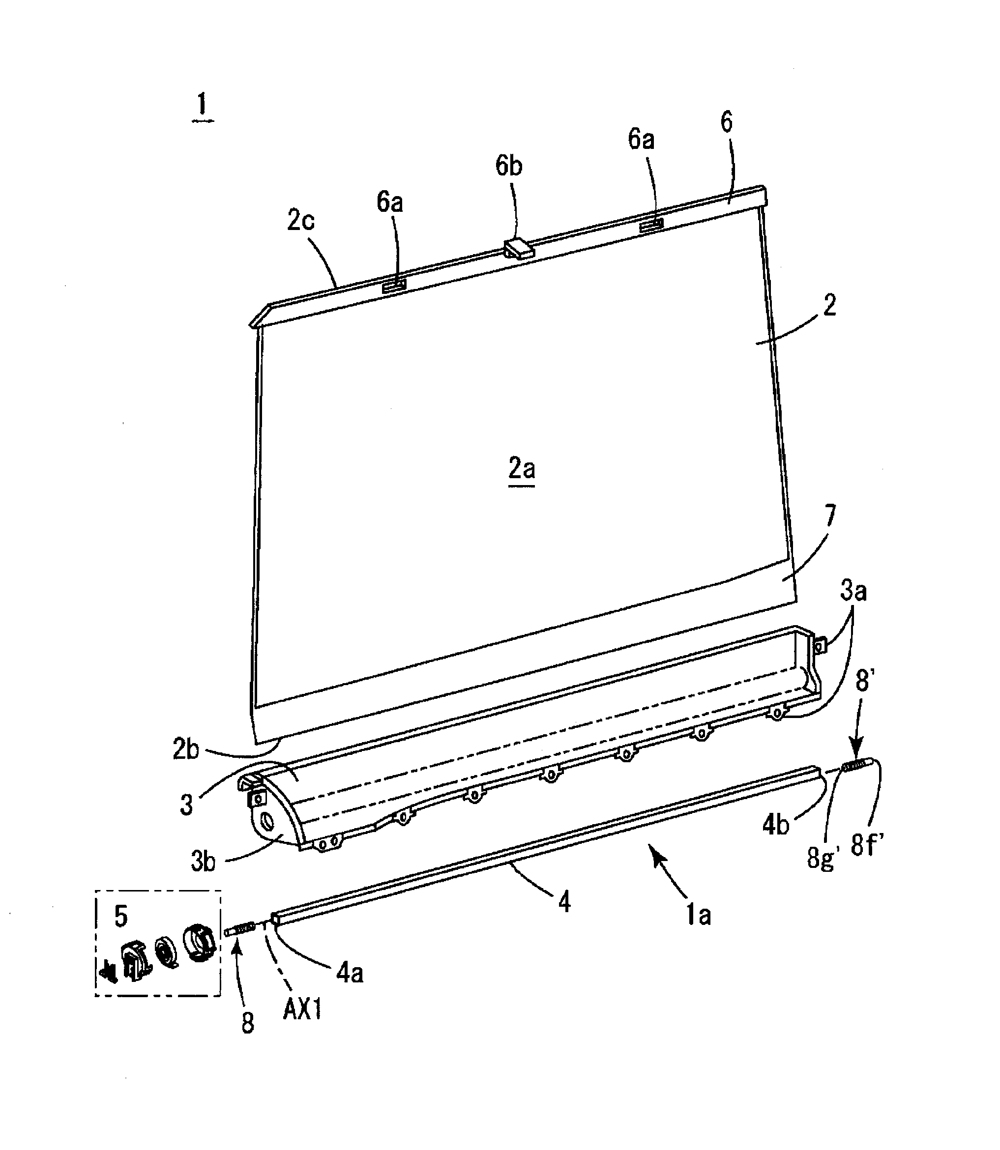
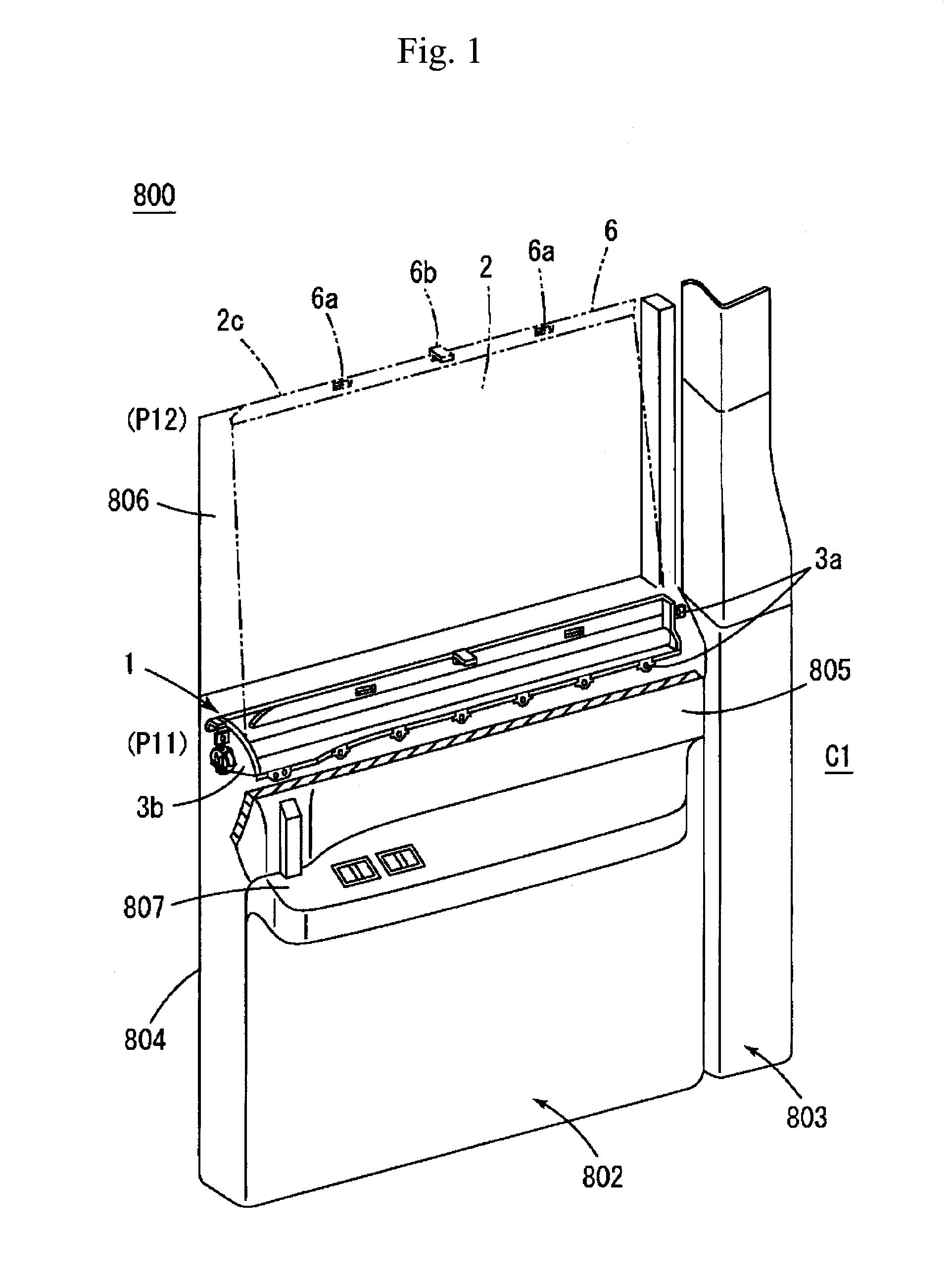
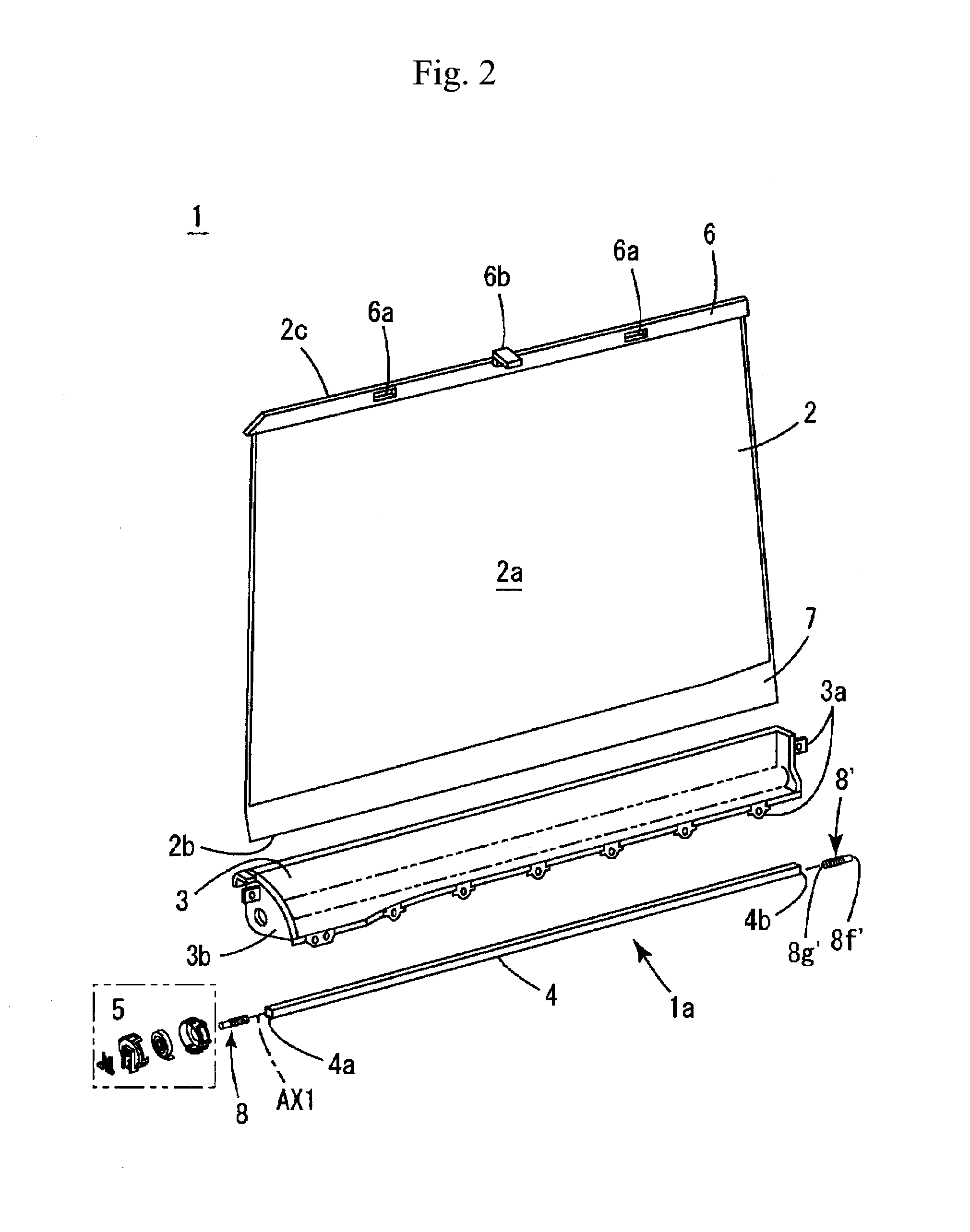
[0053]FIG. 1 shows the first example to use the shading device 1 for vehicle as a sunshade device of a side door (802) of an automobile 800. In the figure, shading device 1 is shown by breaking away an upper portion of the door trim 805. The automobile 800 shown in FIG. 1 is a road running vehicle designed and equipped for being used on a road. In addition, a vehicle cabin C1 is formed around front sheets and rear sheets so that the automobile 800 can be used as a passenger car. A door 802 and a pillar 803 are arranged at a side face portion of the vehicle cabin C1. The shading device 1 is assembled with the door 802 as a sunshade device. The shading device includes the devices called a shade device and a blind device.

[0054]A door panel 804, a door trim 805 and a door window 806 are provided on the door 802, for example. The door panel 804 is a kind of a vehicle body panel made of metal such as a steel sheet. The door trim 805 is an interior material attached to the...

second example

(3) Second Example

[0095]FIGS. 10 to 14 show the second example of the shading device 1.

[0096]FIG. 10 shows, in an exploded perspective view, the cap side of the shading device 1 in a state of removing the clip 109 (locking member 1c).

[0097]FIG. 11A shows the cap side of the shading device 1 when the clip 109 is located at the lock position P1. FIG. 11B shows the cap side of the shading device 1 when the clip 109 is located at the first lock release position P2. FIG. 11C shows the cap side of the shading device 1 when the clip 109 is located at the second lock release position P3.

[0098]FIG. 12A shows a surface of the cap side of the shading device 1 when the shaft portion 1a is locked. FIG. 12B is an end view obtained when the cap 110 (a part of the housing 1d) and the clip 109 are cut at a position corresponding to A4-A4 line in FIG. 12A.

[0099]FIG. 13A shows a surface of the cap side of the shading device 1 when the clip 109 is located at the first lock release position P2. FIG. 13B...

third example

(4) Third Example

[0114]FIG. 15A shows, in a perspective view, the cap side of the shading device 1 when the clip 209 (locking member 1c) is located at the lock position P1 in the third example. FIG. 15B shows, in a perspective view, the cap side of the shading device 1 when the clip 209 is located at the lock release position P2. FIG. 15C shows, in a perspective view, the cap side of the shading device 1 in a state that the clip 209 is removed from a cap 210 (housing 1d).

[0115]The clip 209 (locking member 1c) of the third example is specified to be removed from the housing 1d when the clip 209 is slid from the lock position P1 to an opposite side of the lock release position P2.

[0116]Since the lock portion 8e has an approximately square cross section, the rotation of the shaft portion 1a can be locked at every quarter turn.

[0117]A lock portion 209j, a base body portion 209a, a flexible operating portion 1i, a locking projection 209g (slide engagement portion 1e), a rotation allowing...


PUM


Abstract

The present invention discloses a shading device includes a screen, a shaft portion having a lock portion to be locked, a biasing mechanism, a locking member that is engaged at a lock position with the lock portion, and a housing in which the end portion of the shaft portion is inserted. The housing has a sliding guide portion in which the locking member is slid. The sliding guide portion is capable of guiding the locking member in a direction passing through the lock position and a lock release position, and has a lock position engagement portion for stopping the locking member from sliding at the lock position. The locking member includes a slide engagement portion that engages with the lock position engagement portion at the lock position and an operating portion that can be flexed to release the slide engagement portion from the lock position engagement portion.

Description

CROSS-REFERENCES TO RELATED APPLICATIONS[0001]This Application claims the benefit of priority and is a Continuation application of the prior International Patent Application No. PCT / JP2013 / 081237, with an international filing date of Nov. 20, 2013, which designated the United States, and is related to the Japanese Patent Application No. 2013-013562, filed Jan. 28, 2013, the entire disclosures of all applications are expressly incorporated by reference in their entirety herein.BACKGROUND OF THE INVENTION[0002]1. Field of the Invention[0003]The present invention relates to a shading device installed on a vehicle door or the like.[0004]2. Description of Related Art[0005]On the vehicle door or the like, a sunshade device is provided for blocking sunlight for the purpose of preventing dazzling and for protecting privacy. In the sunshade device for the vehicle door, in many cases, a shading screen is wound and housed inside a door body when not in use. When in use, the screen is drawn out...

Claims


Application Information

Patent Timeline
Patent Type & Authority Patents(United States)
IPC IPC(8): B60J1/20E06B9/40E06B9/62E06B9/80
CPCB60J1/2033B60J1/2038B60J1/2063B60J1/2086E06B9/40E06B9/62E06B9/80E06B2009/802
Inventor WATANABE, KEISUKENISHIURA, TOSHIYATSUCHIMOTO, YOSHIHIROYAGAME, NAOFUMI
Owner HAYASHI TELEMPU CO LTD
Why Eureka
Try Eureka