Blood concentrate detector

a detector and blood concentrate technology, applied in the field of blood concentrate detectors, can solve the problems of frequent calibration, increased work and cost in the cleansing process between patients, and devices that cannot detect small concentrates of blood particles within dialysate solutions, so as to avoid alterations in the characteristics of the solution, minimize adverse effects on the sensor, and avoid calibration.

Inactive Publication Date: 2009-12-17
THOMSON ROBERT JOHN
View PDF3 Cites 41 Cited by
  • Summary
  • Abstract
  • Description
  • Claims
  • Application Information

AI Technical Summary

Benefits of technology

[0011]presence of all blood within tubing.
[0012]By utilizing visible light produced from light emitting diodes (LEDs), creates little to no heat, thus alterations in the characteristics of the solution is avoided unlike blood leak detectors that employ laser or incandescent light.
[0013]Recent developments in international medical equipment standards has required multiple detection levels of blood percentage within intravenous tubing for extracorporeal treatment systems; whereby the equipment is to react differently to differing concentrates of blood such as: indicate, annunciate, shut down. It is envisioned that the requirements will be further refined as the blood detection technology is further developed. In addition to having a blood concentrate detector determine the percentage of blood in solution over as wide a range as possible, it is also desirable to minimize adverse effects upon the sensor do to their environment; such as contact with solution / blood, leakage of solution / blood into mechanical parts, electrical noise interference, ambient light interference, etc. Plus the sensor should be designed in such a manner to avoid the need for calibration and should be easily cleaned without damage. The blood concentrate detector described here is believed to satisfy these requirements and to overcome the shortcomings of prior blood leak detectors.
[0014]In a first embodiment, the invention is a blood concentrate detector comprising a light source emitting light, in a wavelength range of 400 to 800 nm, to an opposing photo-detector with amplification circuitry, housed in an enclosure that can accept an intravenous tube.
[0015]A second embodiment of the invention is a blood concentrate detector comprising a housing having a slotted opening for insertion of the intravenous tube, wherein the slot opening is smaller than the nesting position of the tube, where as the housing acts to secure the tube in place and at the desired optical path between the light emitter and photo-detector receiver.
[0016]A third embodiment of the invention is a blood concentrate detector comprising a housing having a nesting position that forms, and / or allows the tube to form, a biconvex lens when filled with translucent fluid.

Problems solved by technology

Because the solution and blood came in contact with the apparatus, it caused serious hygiene concerns, plus created ample work and costs in the cleansing process between patients.
These devices could not detect small concentrates of blood particles within the dialysate solution.
These were prone to drift, required frequent calibration and are susceptible to ambient light and electrical noise.
Such software and hardware created significant cost to the device, plus was only masking the inherent shortcoming.
Although an improvement over previous devices from the stand point of overcoming the shortcomings of drift, frequent calibrations and ambient conditions, these devices utilize a narrow field of view e.g. 0.03 to 0.06 inch beam width; thus fail to sample a significant portion of the dialysate to determine low concentrates of blood.
Plus these devices employ light in the near infrared range that utilizes a contrast measurement—not a blood absorption measurement, of which this light range is susceptible to like contrast measurements from other contaminants; such as bubbles and micro bubbles.
In addition, these devices require the use of a pop-up vane, which is an opaque material that blocks the light beam when the intravenous tubing is removed.
The pop-up vane, being a mechanical device, is inherently subjected to failure; due to wear and clogging of its actuating mechanism, e.g. spring, rocker, etc.
Plus, given the sticky nature of intravenous fluids and their tendency to leak, would require meticulous cleaning after each application.

Method used


Image

  • Blood concentrate detector
  • Blood concentrate detector
  • Blood concentrate detector

Examples


Embodiment Construction

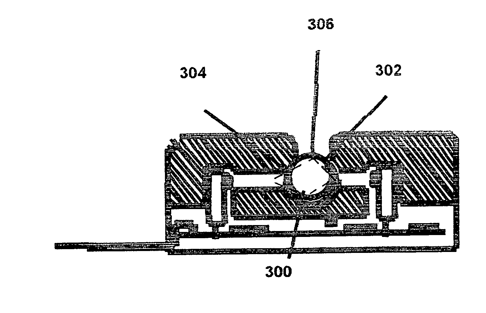
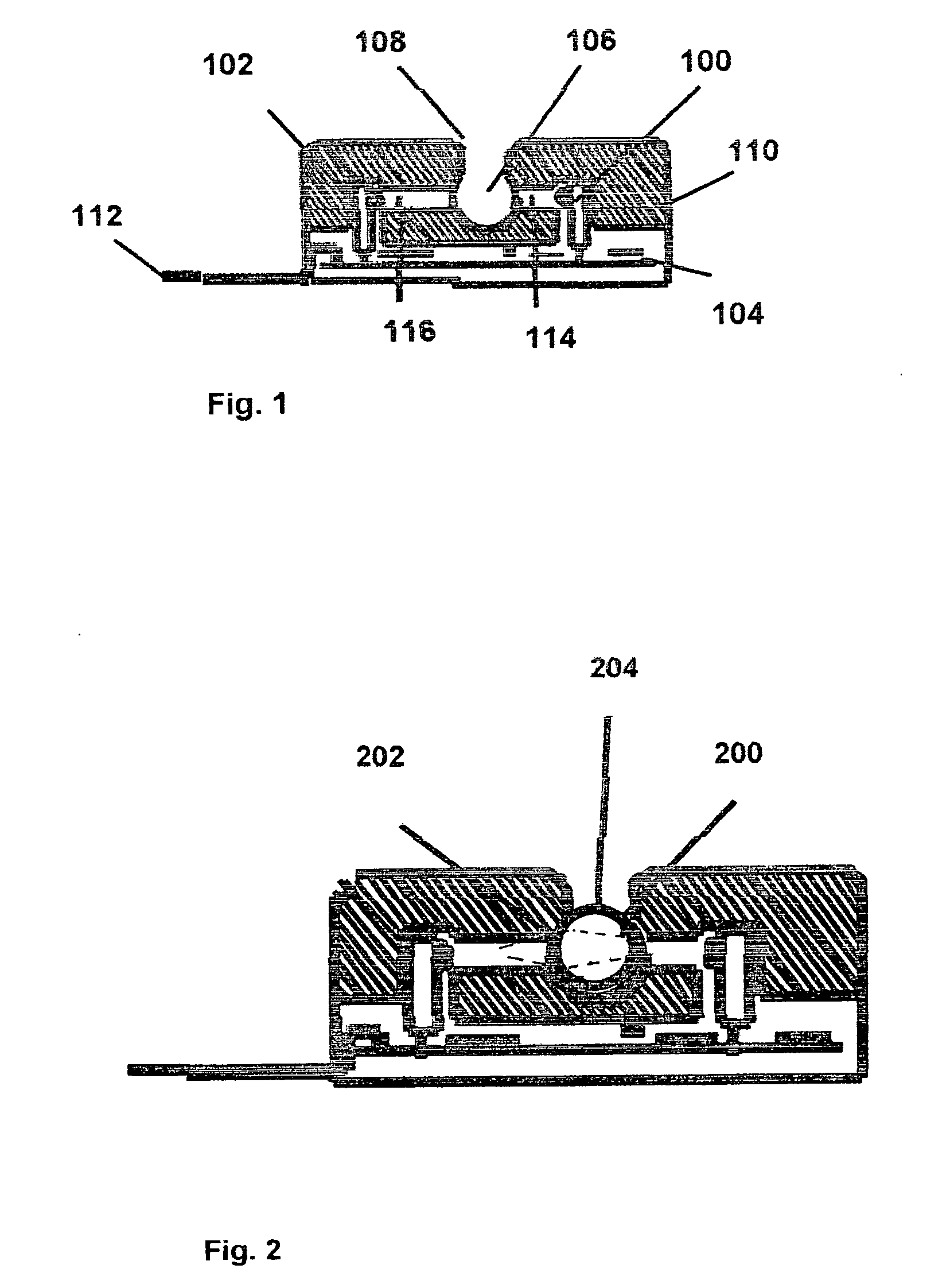
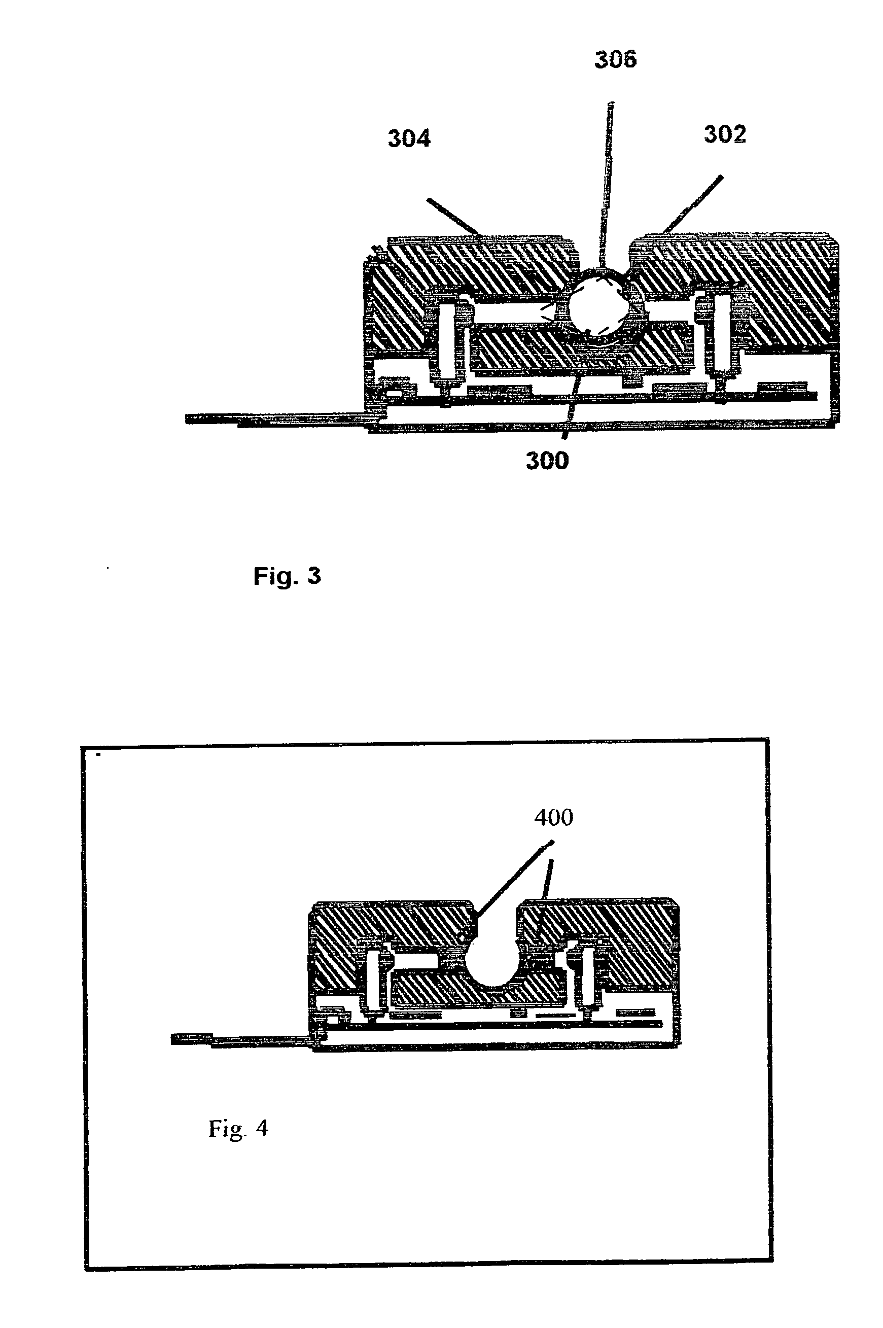
[0047]FIG. 1 shows a perspective view of the blood concentrate detector used in connection with intravenous tubing for extracorporeal treatment system whereas it is desirable to detect the malfunctioning of equipment and / or the misapplication of apparatus used in the medical treatment system. Such equipment malfunctions include, but are not limited to, pump stoppage, pump reverse, filter leakage, filter breakage, circulation interference, etc. Such misapplication of apparatus include, but are not limited to: intravenous tubing not properly inserted or pulled out of the tube cavity (e.g. nesting area, optical pathway); air in tubing due to fluid leakage, dispenser empty, etc.; intravenous tubing kinked; et. FIG. 5 depicts the various states that will manifest as a result of the various malfunctions and / or misapplications described. FIG. 1 depicts an optical system to detect these various states, by way of generating a light 100 and transmitting said light through an aperture 114, acr...


PUM

PropertyMeasurementUnit
wavelengthaaaaaaaaaa
diameteraaaaaaaaaa

Abstract

A blood concentrate detector is disclosed for non-invasive, optical, detection of blood in translucent fluids, within translucent tubes, wherein the fluid is formed into a biconvex lens to 1st disperse the light beam, being emitted through a 0.03 to 0.06 inch orifice, across the inner diameter of the tube, then 2nd for that dispersed light to be refocused, via the fluid acting as a lens in the second half of the tube, and directed through a 0.030 to 0.06 inch aperture on the opposing side for detection purposes; whereas the detector measures the reduction in light energy do to the absorption by blood particles of light being emitted in the visible light range of 400 to 800 nm wavelength. Diffusing the light energy throughout the fluid creates an increase ratio of light energy absorption, whereby the electronic circuit can calculate the percentage of blood concentrate within the fluid.

Description

BACKGROUND[0001]1. Field of Invention[0002]The present invention relates to the non-invasive, optical detection of blood in translucent fluids. In particular, this invention relates to a system of interrelated optical devices, lenses and electronic circuit designed and deployed to detect the intrusion of blood in intravenous tubing for extracorporeal medical devices. More particularly, this invention relates to the detection of blood concentrates within the fluid More particularly yet, this invention relates to improved blood leak detector technology manifesting in increased reliability and accuracy These improvements include; liquid lens technology, proportional light energy absorption properties, electronic circuit stability as well as a means of self-monitoring proper installation of tubing and fluid flow.[0003]2. Prior Art[0004]Early model blood leak detectors used invasive optical means whereby they redirect the flow of dialysate (and blood) pass sensor(s) embedded in the intra...

Claims


Application Information

Patent Timeline
Patent Type & Authority Applications(United States)
IPC IPC(8): G01N33/49
CPCG01N33/49G01N2021/0364G01N21/85
Inventor THOMSON, ROBERT JOHN
Owner THOMSON ROBERT JOHN
Why Eureka
Try Eureka