
Drying Nozzle

a technology of nozzle and nozzle body, which is applied in the direction of drying machines with progressive movements, lighting and heating apparatus, instruments, etc., can solve the problems of increasing the reject rate, facilitate screwing and unscrewing of the cap, and connect and disconnect the supply duct easily and reliably

Active Publication Date: 2009-12-17
ALCON INC
View PDF2 Cites 0 Cited by
  • Summary
  • Abstract
  • Description
  • Claims
  • Application Information

AI Technical Summary

Benefits of technology

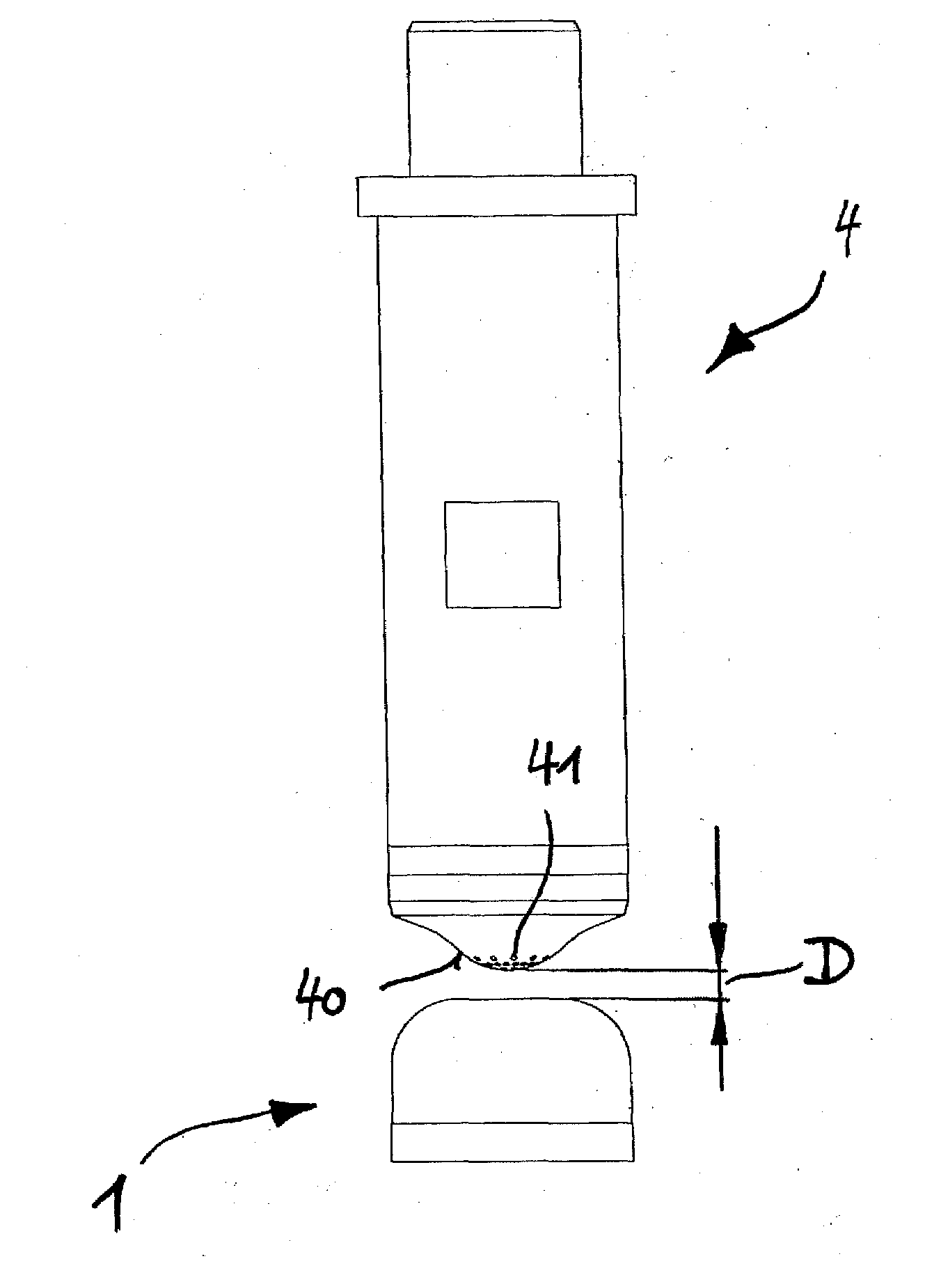
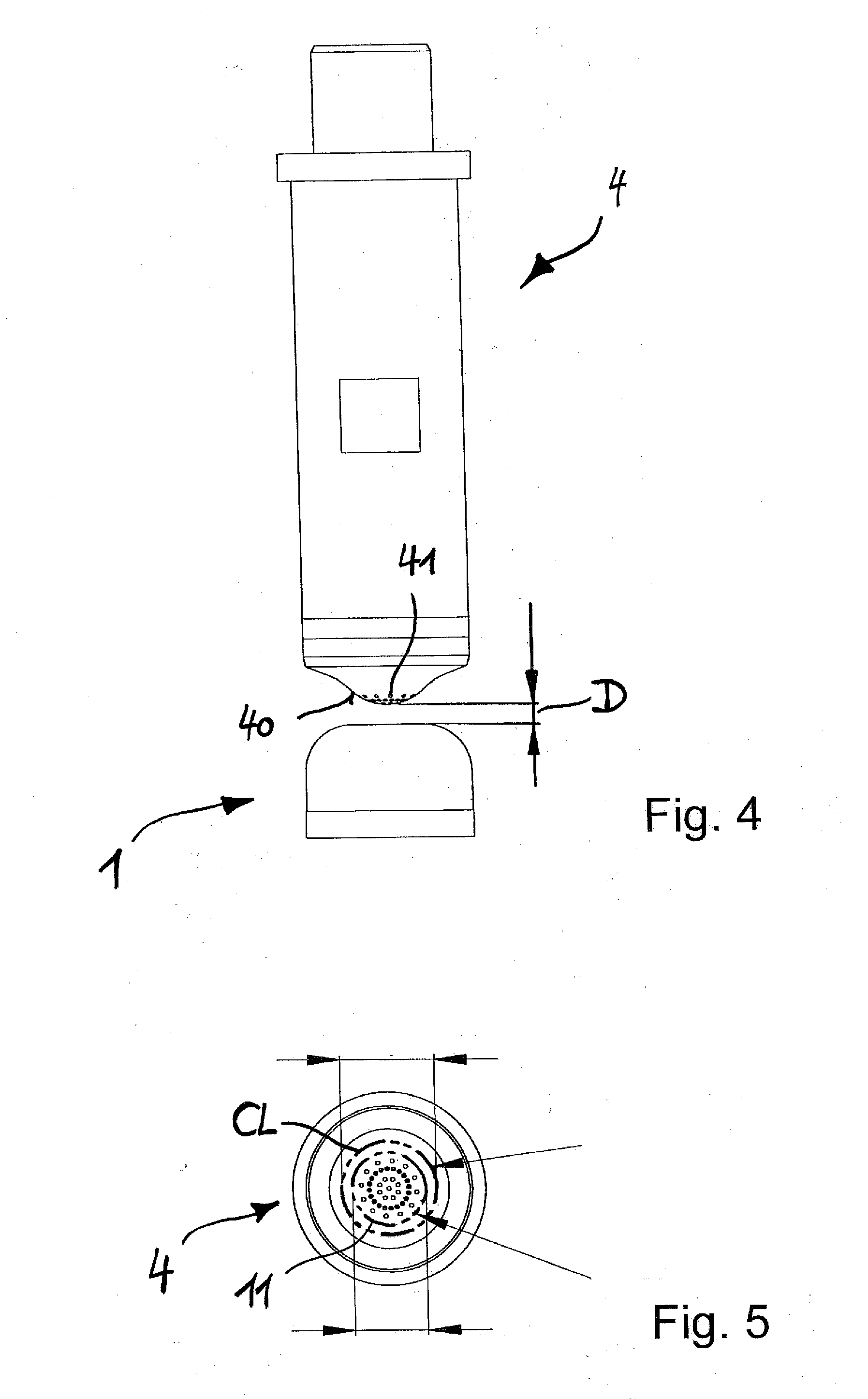
The present invention relates to a drying nozzle for a contact lens that can evenly dry the lens edge, reducing unjustified lens rejections due to water droplets or the like. The nozzle has a continuous annular outlet gap with a predetermined width, through which pressurized air can be supplied to the lens. The nozzle is easy to assemble and disassemble, and it can be made from a non-corrosive material. The invention also includes a process for inspecting the peripheral region of a lens by drying it with the nozzle and analyzing it with image analysis. The technical effects of the invention are improved production efficiency and reduced defective lens production.

Problems solved by technology

However, due to the fact that the contact lens the edge of which is to be inspected is still wet (e.g. water droplets adhere to the lens), the automatic inspection system may detect a lens as being defective although it is not.
Since dark portions at the lens edge are interpreted as representing a defect of the lens edge, the lens may be rejected although the lens edge indeed is not defective, thus unnecessarily increasing the reject rate.
Previous attempts have been made to improve this misinterpretation by drying the contact lens by means of application of pressurized air with the aid of nozzles having discrete openings, however, this has still resulted in portions at the lens edge which are represented darker so that lenses have been rejected as being defective although they are not.

Method used


Image

  • Drying Nozzle
  • Drying Nozzle
  • Drying Nozzle

Examples


Embodiment Construction

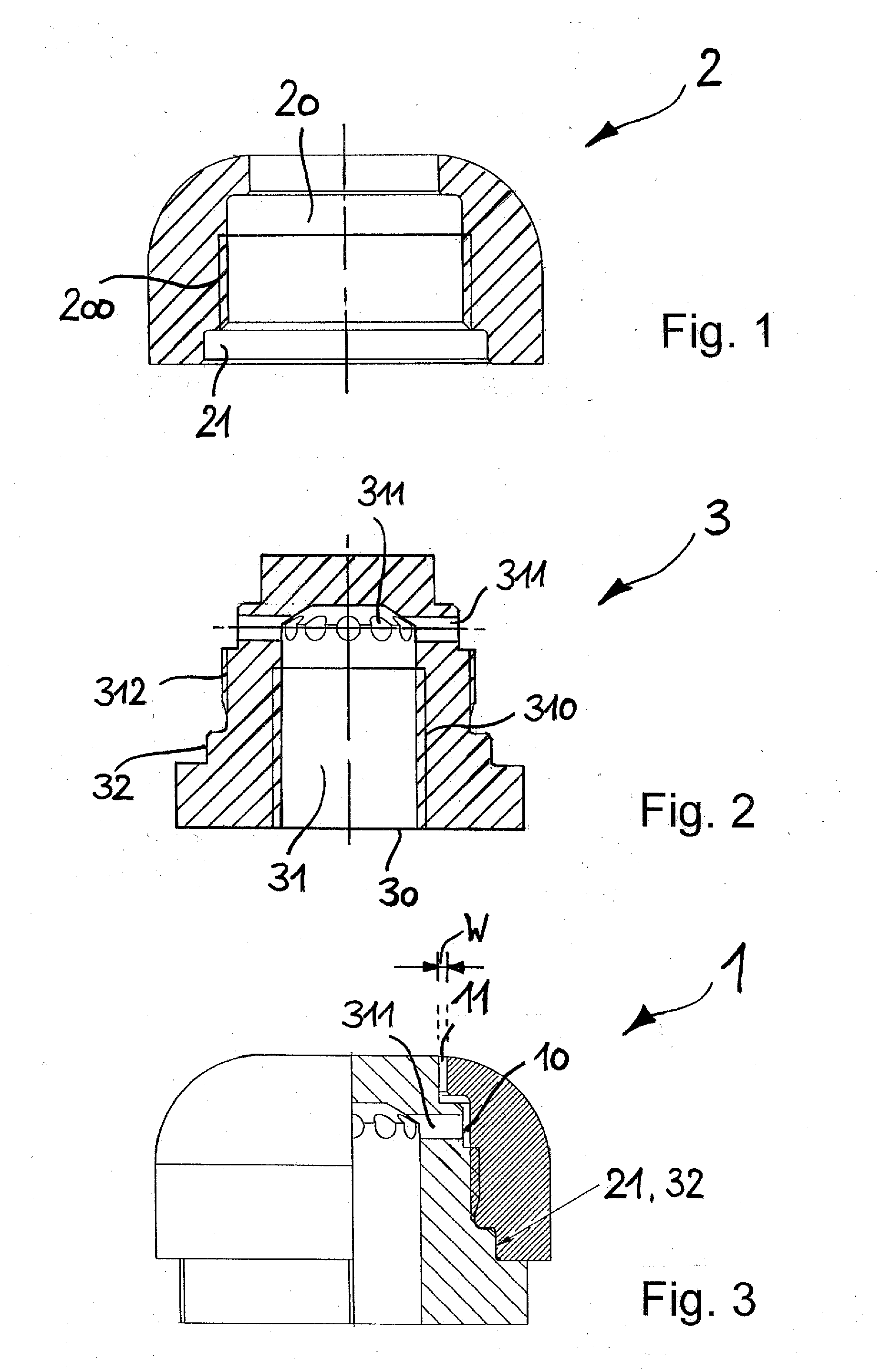
[0026]An embodiment of the drying nozzle 1 according to the invention is shown in FIGS. 1-3, with FIG. 1 showing only the cap 2 of the nozzle, FIG. 2 showing only the body 3 of the nozzle, and FIG. 3 showing the nozzle 1 comprising both the cap 2 and the body 3 in the assembled state.

[0027]The cap 2 comprises a centrally arranged cylindrical bore 20 having portions with different inner diameters. One of these portions is provided with an internal thread 200 allowing to screw cap 2 onto body 3. Body 3 is provided with a corresponding external thread on body 3, accordingly. Cylindrical bore 20 further comprises a fitting portion 21 having an inner diameter which corresponds to the outer diameter of a corresponding fitting portion of body 3 in order to cause the cap 2 to get centered during screwing of cap 2 onto body 3.

[0028]Body 3 has an inlet 30 and a feed channel 31 defined by a cylindrical bore. Feed channel 31 is at least partly provided with an internal thread 310 allowing to co...


PUM

PropertyMeasurementUnit
widthaaaaaaaaaa
widthaaaaaaaaaa
widthaaaaaaaaaa

Abstract

A drying nozzle (1) for drying a peripheral portion of an ophthalmic lens (CL), in particular a contact lens, comprises an inlet (30) for the supply of a pressurized gas and a continuous annular outlet gap (11) having a predetermined width (W) through which the pressurized air is capable of being supplied to the peripheral portion of the ophthalmic lens (CL).

Description

[0001]This application claims benefit under 35 U.S.C. §119 of European Patent Application No. 08157781.9, filed on Jun. 06, 2008,the contents of which are incorporated herein by reference in its entirety.FIELD OF THE INVENTION[0002]The present invention relates to a drying nozzle for drying a peripheral portion of an ophthalmic lens, in particular a contact lens.BACKGROUND OF THE INVENTION[0003]In the production of contact lenses the lenses are typically automatically inspected for defects in the optical zone as well as in the peripheral portion of the lens, since the peripheral portion and in particular the lens edge greatly affects the wearing comfort that is experienced by the user. Contact lenses which are defective either in the optical zone or in the peripheral portion are rejected, at least if predetermined threshold values for identifying such defects are exceeded.[0004]In a known mass production process of contact lenses a viscous starting material is dispensed into a femal...

Claims


Application Information

Patent Timeline
Patent Type & Authority Applications(United States)
IPC IPC(8): G01N21/00F26B21/00
CPCF26B21/004B29D11/00125
Inventor BAYER, ALEXANDERBROTZMANN, PETER
Owner ALCON INC
Learn More