Panoramic imaging apparatus and image processing method for panoramic imaging

a panoramic imaging and imaging apparatus technology, applied in the field of panoramic imaging apparatus and image processing method, can solve the problem of limited application to observing the entire tooth row, and achieve the effect of convenient use for interpreting panoramic images

Inactive Publication Date: 2009-12-17
AXION JAPAN
View PDF17 Cites 77 Cited by
  • Summary
  • Abstract
  • Description
  • Claims
  • Application Information

AI Technical Summary

Benefits of technology

[0013]According to the present invention provides a panoramic imaging apparatus which is able to provide any high-resolution panoramic images of focused sections in the depth direction of a tooth row and the gum-ridge, together with their distance information, using image data acquired by X-ray panoramic imaging to be carried out only one time from a specified section along a patient's tooth row, thus being easier in use for interpreting the panoramic images.

Problems solved by technology

Hence the resolution of panoramic images reconstructed along the tooth row from acquired images by the scanner is not so high, which has limited its application to observing the entire tooth row.

Method used


Image

  • Panoramic imaging apparatus and image processing method for panoramic imaging
  • Panoramic imaging apparatus and image processing method for panoramic imaging
  • Panoramic imaging apparatus and image processing method for panoramic imaging

Examples


first embodiment

[0015]Referring to FIGS. 1-31, a first embodiment of the panoramic imaging apparatus according to the present invention will now be described.

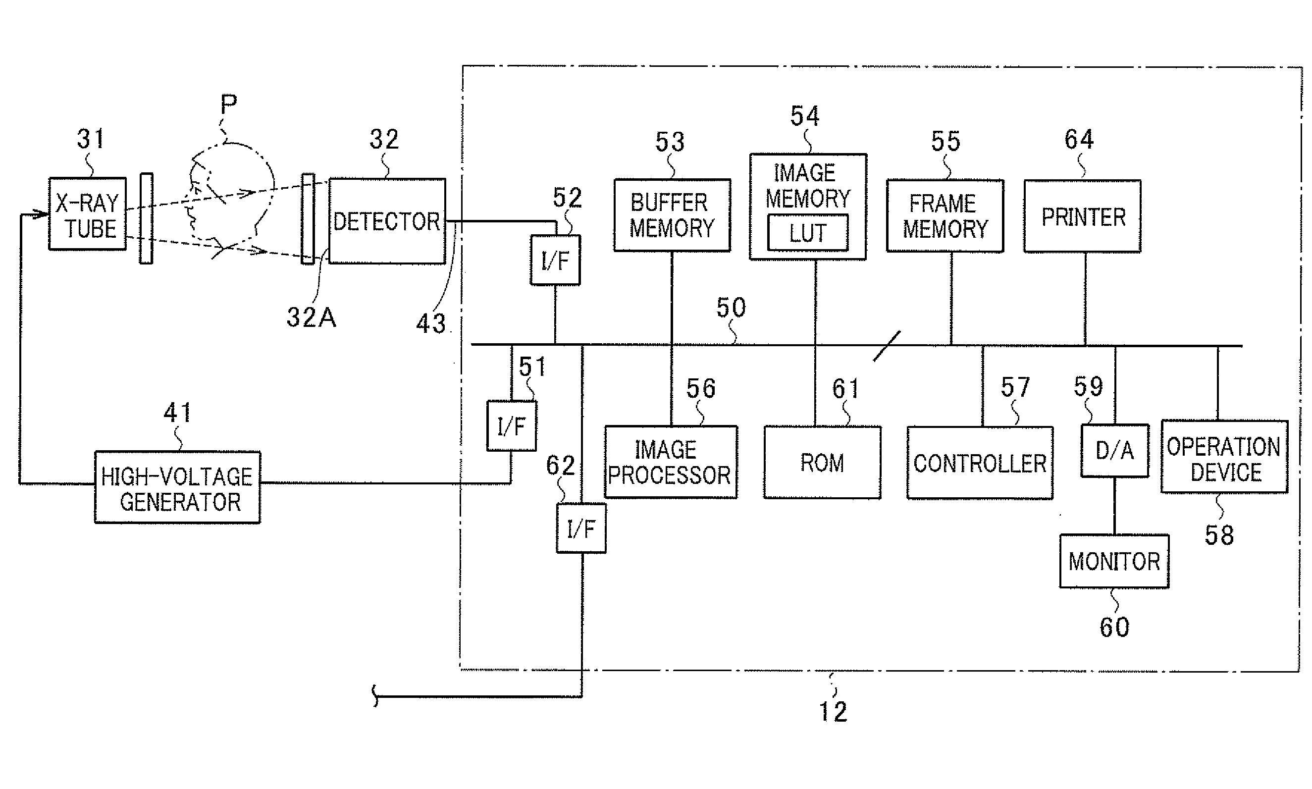
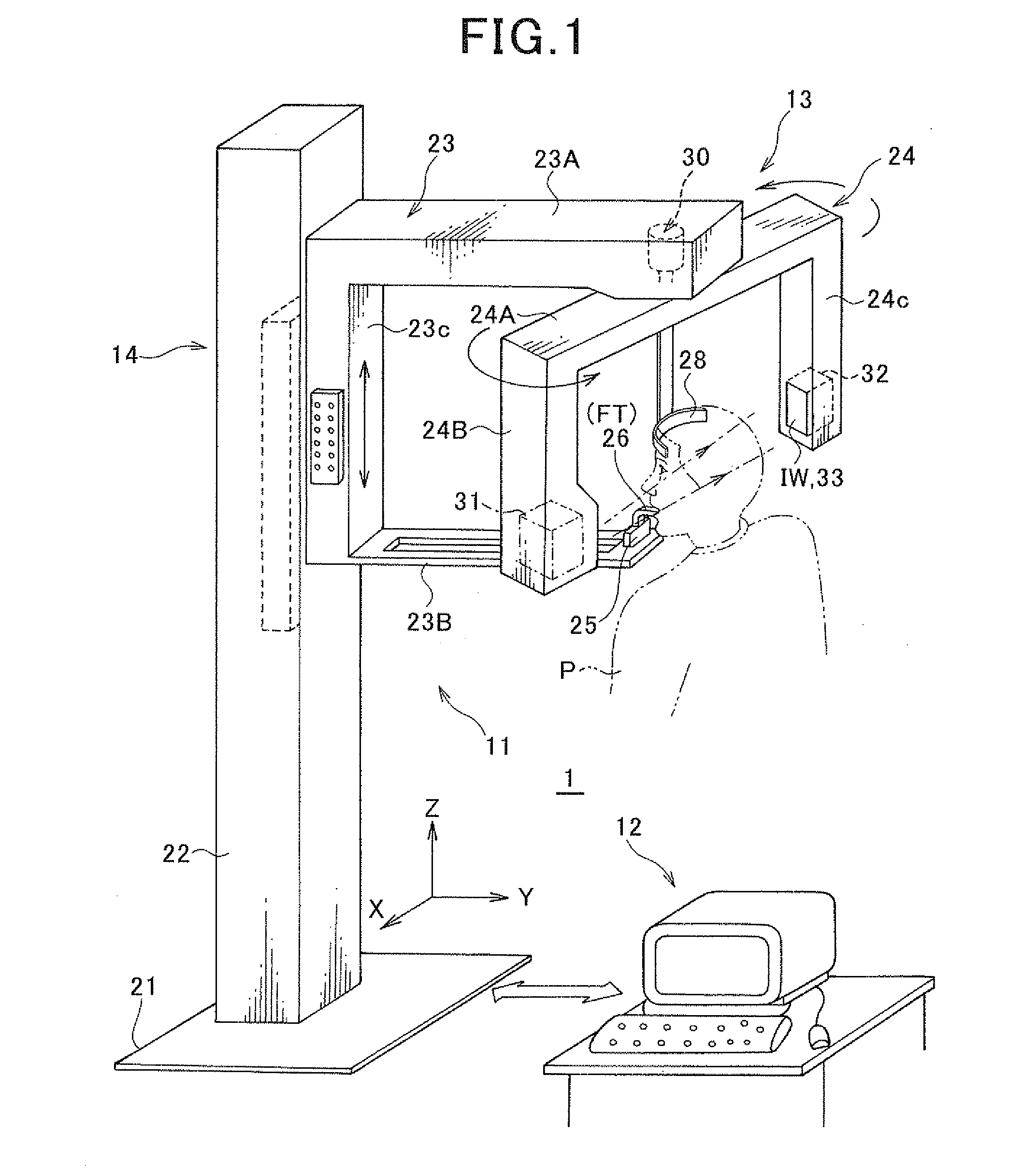
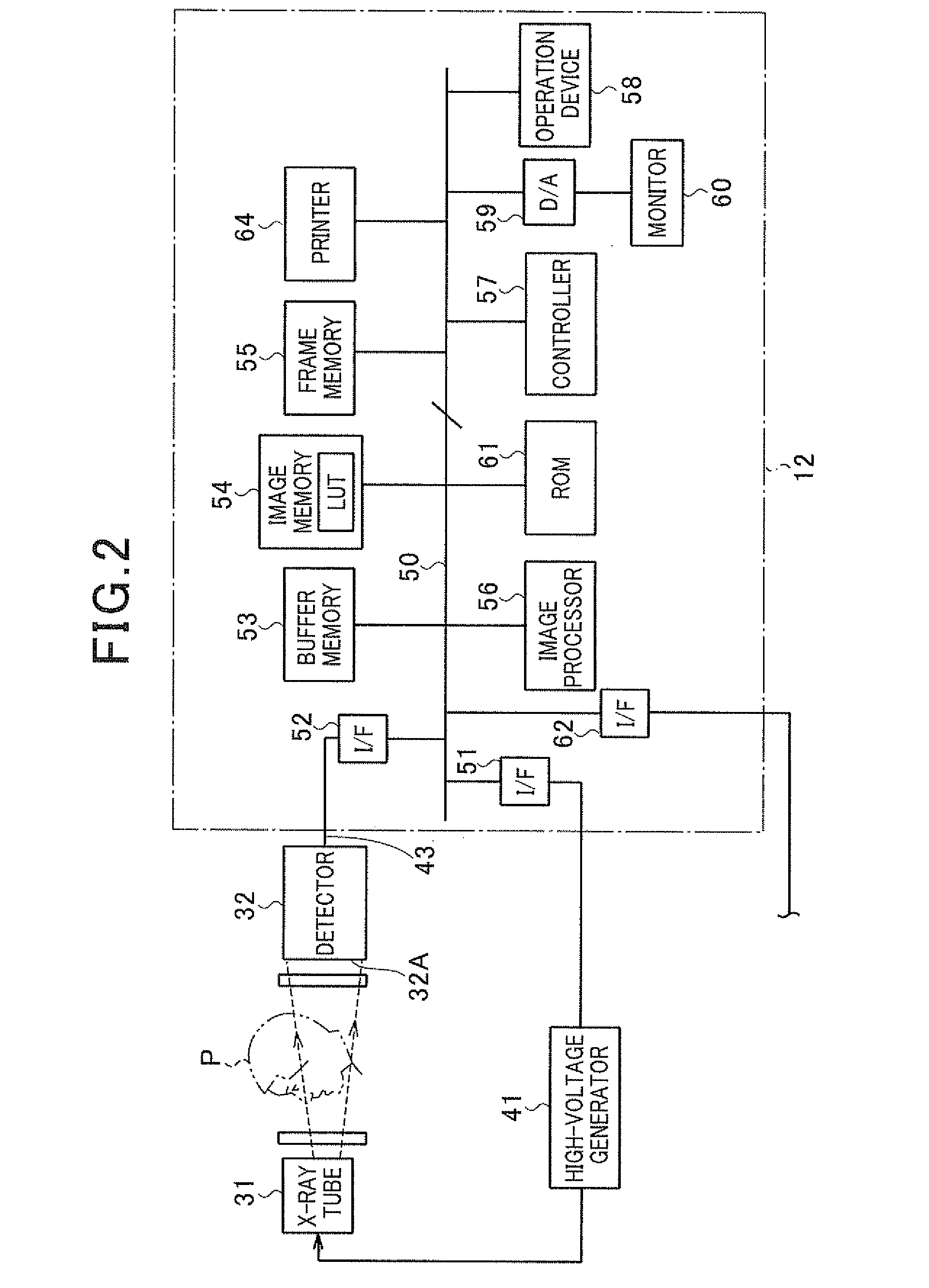
[0016]FIG. 1 shows the appearance of a panoramic imaging apparatus 1 according to the present embodiment. As shown, this panoramic imaging apparatus 1 comprises a chassis 11 and a control / calculation unit 12 composed of a computer system, where the chassis 11 allows an object (patient) P being examined to stand up to acquire black-and-white original image data for producing panoramic images, and the control / calculation unit 12 controls data acquisition carried out by the chassis 11, takes in the acquired data to produce panoramic images, and post-processes the produced panoramic images interactively with an operator (doctor or engineer).

[0017]The chassis 11 is provided with a stand unit 13 and an imaging unit 14 which can be moved up and down in relation to the stand unit 13. The stand unit 13 is provided with a base 21 fixed on the floor and ...

second embodiment

[0173]Referring to FIGS. 32-38, a second embodiment of the panoramic imaging apparatus according to the present invention will now be described.

[0174]The panoramic imaging apparatus according to the present embodiment is characteristic of performing a process (contrast enhancement process) for enhancing the contrast of images of two-dimensional regions specified by ROIs, that is, images (original images) of local regions on the panoramic image produced at the foregoing step 39 (in FIG. 19); the contrast of enlarged original images subjected to enlargement display at step S42 (in FIG. 20); and the contrast of focus-optimized images to be displayed at steps S46, S50, and S54 (in FIG. 20). The other configurations and processes are the same or similar as or to those in the first embodiment. Hence, the identical components to those in the first embodiment are given the same reference numbers.

[0175]The contrast enhancement will not always be limited to the application to two-dimensional ...

third embodiment

[0270]Referring to FIGS. 39 and 40, a third embodiment of the panoramic imaging apparatus according to the present invention will now be described. The similar hardware components to those described already are given the same reference numerals as those.

[0271]Even if a patient's tooth row is far from an ideal one such that, for example, adjacent teeth are overlapped with each other, the present panoramic imaging apparatus is able to image how those tooth are overlapped and the anteroposterior relationship of those tooth in a proper manner. In the past, there is an overlap between teeth, the overlap portion appears in white in a panoramic image, making the interpretation impossible or lowering accuracy in the interpretation.

[0272]This problem can be solved by performing a later-described effective width control process at a proper timing during the interpretation process shown in FIGS. 19 and 20 or after the interpretation process.

[0273]This effective width control process is to cont...


PUM


Abstract

A panoramic imaging apparatus is provided, which is able to freely display a focus-optimized internal structural image of the tooth row depending on a position using image data acquired by only one-time X-ray panoramic imaging from an arbitrary section along a patient's tooth row.
The panoramic imaging apparatus comprise an X-ray source (31) and a detector (32) outputting a digital electrical signal depending on an incident X-ray at a constant frame rate. This apparatus further comprises means (24) for moving a pair of the X-ray source and the detector around an object in a state where the X-ray source and the detector are opposed to each other with the object located therebetween, means (54) for sequentially storing, as frame data, the electrical signal outputted by the detector, means (56) for producing a panoramic image of a desired section of the object based on the frame data, and means (56, 57, 58) for producing a partial sectional image using the frame data, the partial sectional image being an image of a partial region specified on the panoramic image and being focused depending on a desired position in an imaging space.

Description

TECHNICAL FIELD[0001]The present invention relates to a panoramic imaging apparatus for imaging panoramic images of a specified part of an object being imaged, such as a row of teeth, and a method of processing images for panoramic imaging, and in particular, to a panoramic imaging apparatus provided with a pair of an X-ray source and a digital type X-ray detector, which are arranged to be opposed to each other and to have an object located between the X-ray source and the X-ray detector, and with this arrangement, the paired X-ray source and the X-ray detector are moved along a predetermined orbit around the object, during which time X-rays radiated from the X-ray source and transmitted through the object are detected by the X-ray detector at intervals, so that digital X-ray transmission data detected by the X-ray detector are used to produce panoramic images of the object, and a method of processing images for the imaging processing.BACKGROUND ART[0002]Due to, in part, recent chan...

Claims


Application Information

Patent Timeline
Patent Type & Authority Applications(United States)
IPC IPC(8): G06K9/00
CPCA61B6/583A61B6/14
Inventor OGAWA, KOICHIYAMAKAWA, TSUTOMUSUE, TAKASHI
Owner AXION JAPAN
Why Eureka
Try Eureka