Image processing apparatus, imaging apparatus, image processing method and recording medium
Active Publication Date: 2009-12-17
FUJIFILM CORP
View PDF5 Cites 62 Cited by
Summary
Abstract
Description
Claims
Application Information
AI Technical Summary
This helps you quickly interpret patents by identifying the three key elements:
Problems solved by technology
Method used
Benefits of technology
Benefits of technology
[0017]According to the first aspect of the present invention, a plurality of images are acquired while varying the focus position of the lens, and sharpness on each pixel of the acquired plurality of images is calculated. The first reference value, which indicates an image of the plurality of images which includes the pixel whose sharpness is the highest, is calculated on a pixel basis. The second reference value is calculated by spatially smoothing the calculated first reference value based on the first reference value on adjacent pixels. The plurality of images are image-processed based on the calculated second reference value. This allows the transition between the second reference values representing an in-focus distribution to be smoothed. In other words, smoothness in a gradational level direction and / or in a spatial direction can be attained. Therefore, a naturally processed image can be acquired.
[0018]Here, the image processing device may image-process the plurality of images acquired by the image acquiring device based on the second reference values calculated by the second reference value calculating device to generate an omni-focus image where every part of the image is in focus. Accordingly, a natural omni-focus image can be acquired. “To generate an omni-focus image where every part of the image is in focus” means to generate a synthesized image by combining parts where focus is obtained (in-focus parts) in respective images acquired by the image acquiring device. It is not required, in the present invention, to take the focus in parts where focus is not obtained (out-of-focus parts) in all of the plurality of acquired images. That is, when a part A is out of focus in all of the images, the part A remains out of focus even though the omni-focus processing is performed.
[0029]In the image processing apparatus of the sixth aspect, a low resolution map having smaller number of samples is generated by weighted-averaging the first reference values in the prescribed area and the second reference value is calculated by spatially smoothing the generated low resolution map. This allows the processing to become fast and the memory to be conserved.
[0038]According to the present invention, a region having high contrast can be stably judged as an in-focus region, and thus a synthesized image having smooth gradation can be acquired.
Problems solved by technology
H06-311411 uses the region between pixels which have a contrast equal to or higher than a prescribed contrast and form a “pair” as an in-focus region, causing a problem of lacking in stability.
More specifically, if a misjudgment is made when a signal is detected due to noise or the like on a pixel other than the pixel on which a signal should be detected to form the pair, a problem is caused where a high contrast region cannot be judged as the in-focus region.
H06-311411, variation in pixel values is abrupt at a boundary between an in-focus region and an out-of-focus region, causing a problem of discontinuous gradation levels and an unnatural synthesized image.
In the method in which sharpness calculated by a differential filter or the like on an image basis or a pixel basis is used to judge which image is most focused among the focus-bracketed images on a pixel basis and, based on the result, a synthesized weighted coefficient for the omni-focus processing or a blurring amount for blur enhancement processing is calculated, an in-focus judgment result is merely acquired based on the sharpness on a pixel basis, which causes a problem that the in-focus judgment is apt to result in a spatially discontinuous value and it is not unusual that a desired value cannot be acquired.
Method used
Image
Click on the blue label to locate the original text in one second.
Reading with bidirectional positioning of images and text.
Examples
first exemplary embodiment
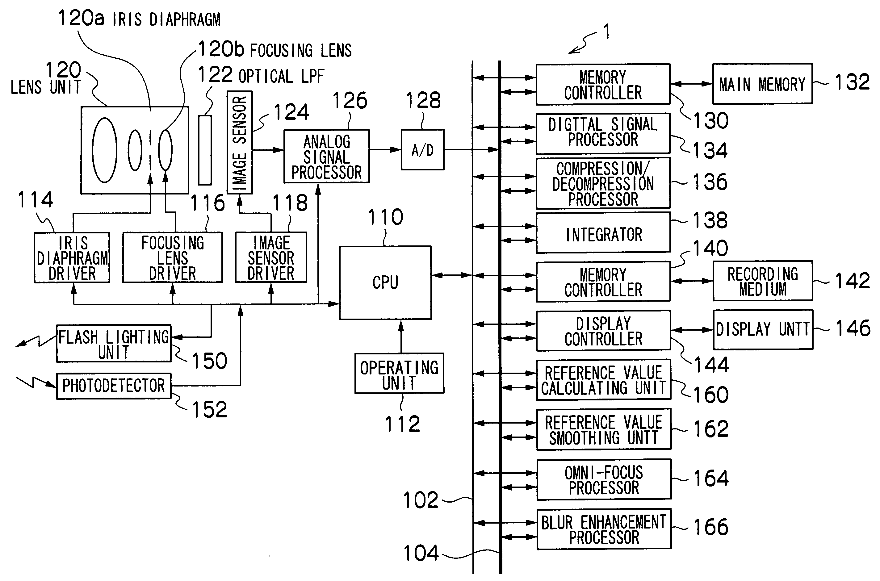
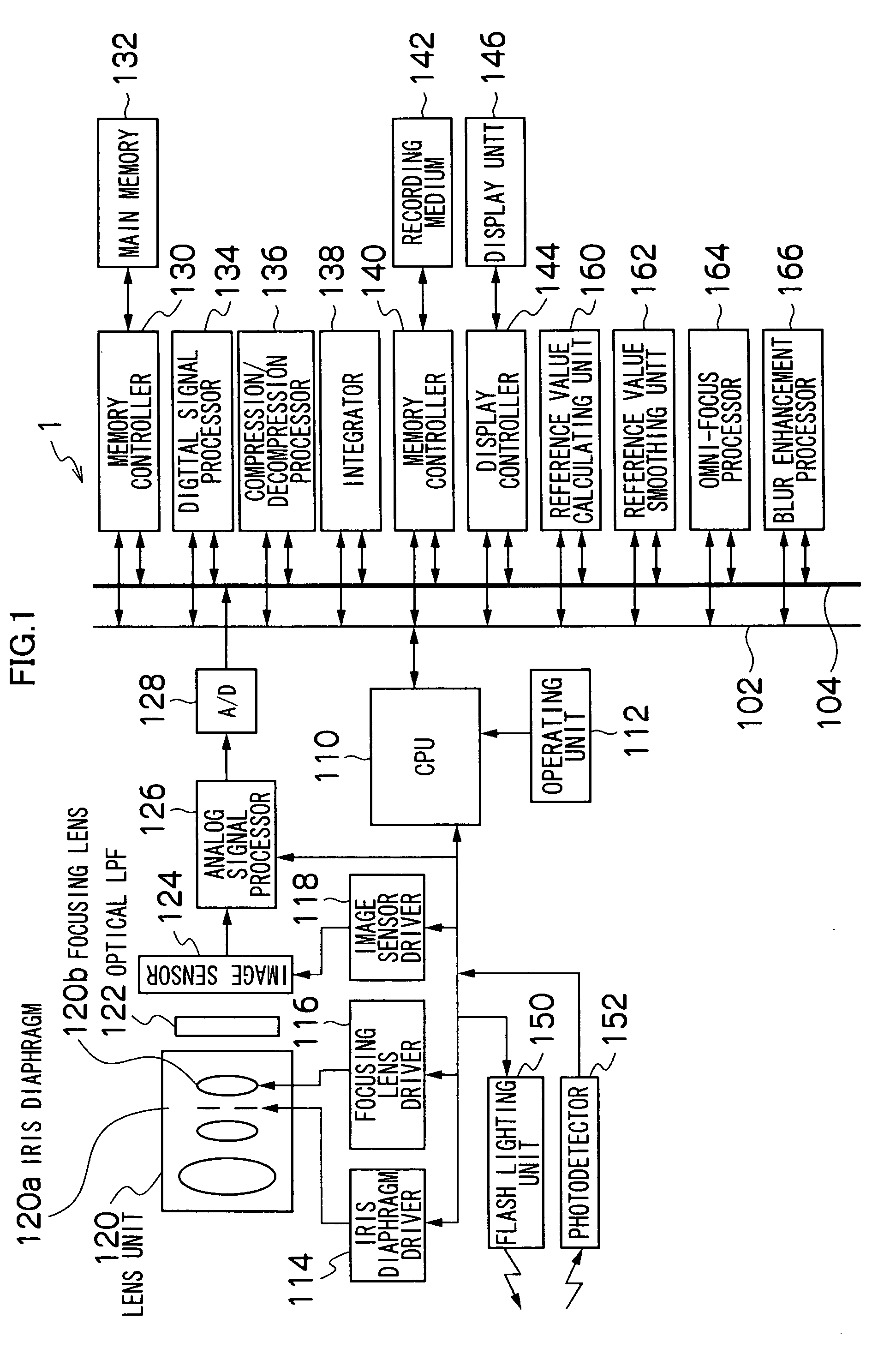
[0058]FIG. 1 is a block diagram schematically showing the internal configuration of a digital camera 1 according to a first exemplary embodiment.
[0059]As shown in the figure, the digital camera 1 principally includes a CPU 110, an operating unit (a shutter release button, a power / mode-selector switch, a mode selector dial, a zooming button, a cross button, a menu / OK button, a DISP button, a BACK button etc.) 112, an iris diaphragm driver 114, a focusing lens driver 116, an image sensor driver 118, a lens unit 120, an optical low-pass filter (LPF) 122, an image sensor 124, an analog signal processor (CDS / AMP) 126, an A / D convertor 128, a memory controller 130, a main memory 132, a digital signal processor 134, a compression / decompression processor 136, an integrator 138, a memory controller 140, a recording medium 142, a display controller 144, a display unit 146, a flash lighting, unit 150, a photodetector 152, a reference value calculating unit 160, a reference value smoothing unit...
second exemplary embodiment
[0132]Since the image number whose sharpness is the highest is used as the first reference value according to the first exemplary embodiment, the same result is acquired irrespective of the level of sharpness provided that the sharpness is the highest. For instance, in the changing point of the edge shown in FIG. 18, the sharpness of the image 1 is 8. However, even if the sharpness is 16 or 1, the sharpness of the image 1 is still highest when being compared with the sharpness of the image 2.
[0133]However, in an actual image, the stronger the edge is, the higher the possibility of in-focus near the pixel is. Therefore, in order to perform more precise in-focus judgment, it is better to perform spatial smoothing in consideration of the level of sharpness.
[0134]According to a second exemplary embodiment, spatial smoothing is performed in consideration of the level of the sharpness by representing the first reference value as a two dimensional vector (sharpness vector) including the im...
PUM
Abstract
Sharpness is calculated in all of focus-bracketed images on a pixel basis. Then, a first reference value indicating an image of the plurality of images to which a pixel whose sharpness is the highest among the pixels located on the identical positions in the plurality of images belongs is obtained on each pixel of the images, and a second reference value is calculated based on the first reference value on each pixel by spatially smoothing the first reference value on each pixel based on the first reference values on adjacent pixels. The focus-bracketed images are processed based on the second reference values to generate an omni-focus image or a blur-enhanced image. Accordingly, it is possible to judge a region having high contrast as an in-focus region and acquire a synthesized image having smooth gradation.
Description
BACKGROUND OF THE INVENTION[0001]1. Field of the Invention[0002]The present invention relates to an image processing apparatus, an imaging apparatus, and a range image generating method and a program, more particularly, to the image processing apparatus, the imaging apparatus, and the range image generating method and the program which can acquire an omni-focus image or a blur-enhanced image by focus bracketing.[0003]2. Description of the Related Art[0004]As a technique for acquiring an omni-focus image using a plurality of images acquired by focus bracketing (hereinafter referred to as focus-bracketed images), which consecutively captures object images while varying the focus position of a lens, Japanese Patent Application Laid-Open No. H06-311411 discloses a technique for generating a synthesized image without blurredness by judging contrast on each pixel in the focus-bracketed image using a differential filter (see SA-SA2 in FIG. 17), determining a region between pixels which hav...
Claims
Application Information
Patent Timeline
Application Date:The date an application was filed.
Publication Date:The date a patent or application was officially published.
First Publication Date:The earliest publication date of a patent with the same application number.
Issue Date:Publication date of the patent grant document.
PCT Entry Date:The Entry date of PCT National Phase.
Estimated Expiry Date:The statutory expiry date of a patent right according to the Patent Law, and it is the longest term of protection that the patent right can achieve without the termination of the patent right due to other reasons(Term extension factor has been taken into account ).
Invalid Date:Actual expiry date is based on effective date or publication date of legal transaction data of invalid patent.

