Image forming unit and image forming apparatus

a technology of image forming unit and apparatus, which is applied in the direction of electrographic process apparatus, instruments, corona discharge, etc., can solve the problems of abnormal electric discharge noise, increased cost, and complicated structure, and achieve the effect of simplifying structure and suppressing abnormal discharg

Active Publication Date: 2009-12-17
KONICA MINOLTA BUSINESS TECH INC
View PDF4 Cites 5 Cited by
  • Summary
  • Abstract
  • Description
  • Claims
  • Application Information

AI Technical Summary

Benefits of technology

[0010]The charging roller rotates following the rotation of the photoconductor. Therefore, adhering substances such as toners and toner post-processing agents hardly accumulate on the contact portion between the photoconductor and the charging roller. This suppresses abnormal discharge due to the adhering substances.
[0011]Therefore, it becomes possible to electrically charge the photoconductor with a simplified structure and to prevent adhering substances from accumulating on the contact portion between the photoconductor and the charging roller.

Problems solved by technology

However, cost has increased in the case of the firstly-stated conventional image forming unit where the charging roller is provided with the shaft.
Also, the structure becomes complicated because members such as springs are required so as to bring the charging roller in pressure contact with the photoconductor.
In the case of the secondly-stated conventional image forming unit where the charging sheet is brought into contact with the photoconductor, there has been a problem that image noises are generated by abnormal electric discharges due to deposits.

Method used


Image

  • Image forming unit and image forming apparatus
  • Image forming unit and image forming apparatus
  • Image forming unit and image forming apparatus

Examples


first embodiment

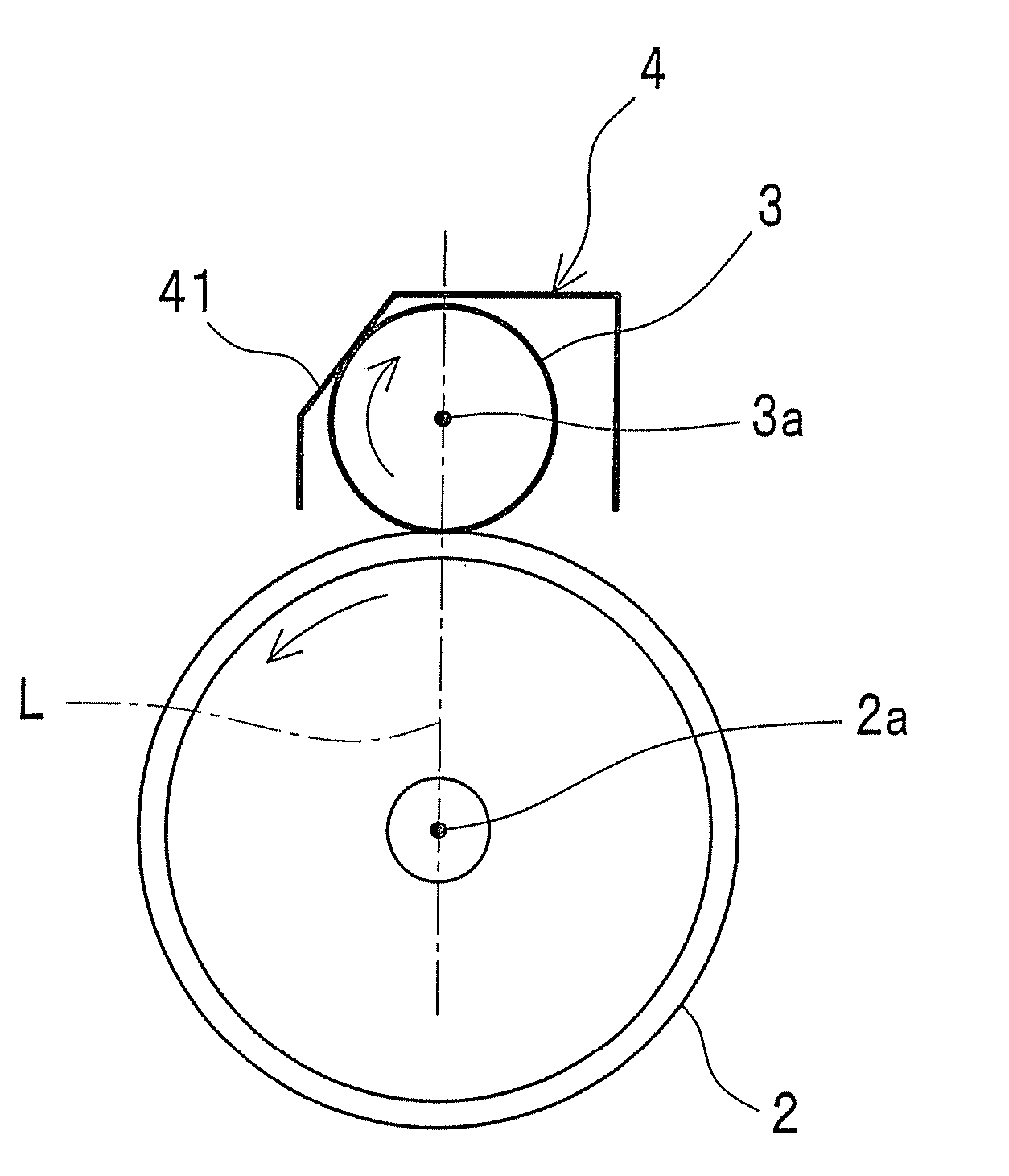
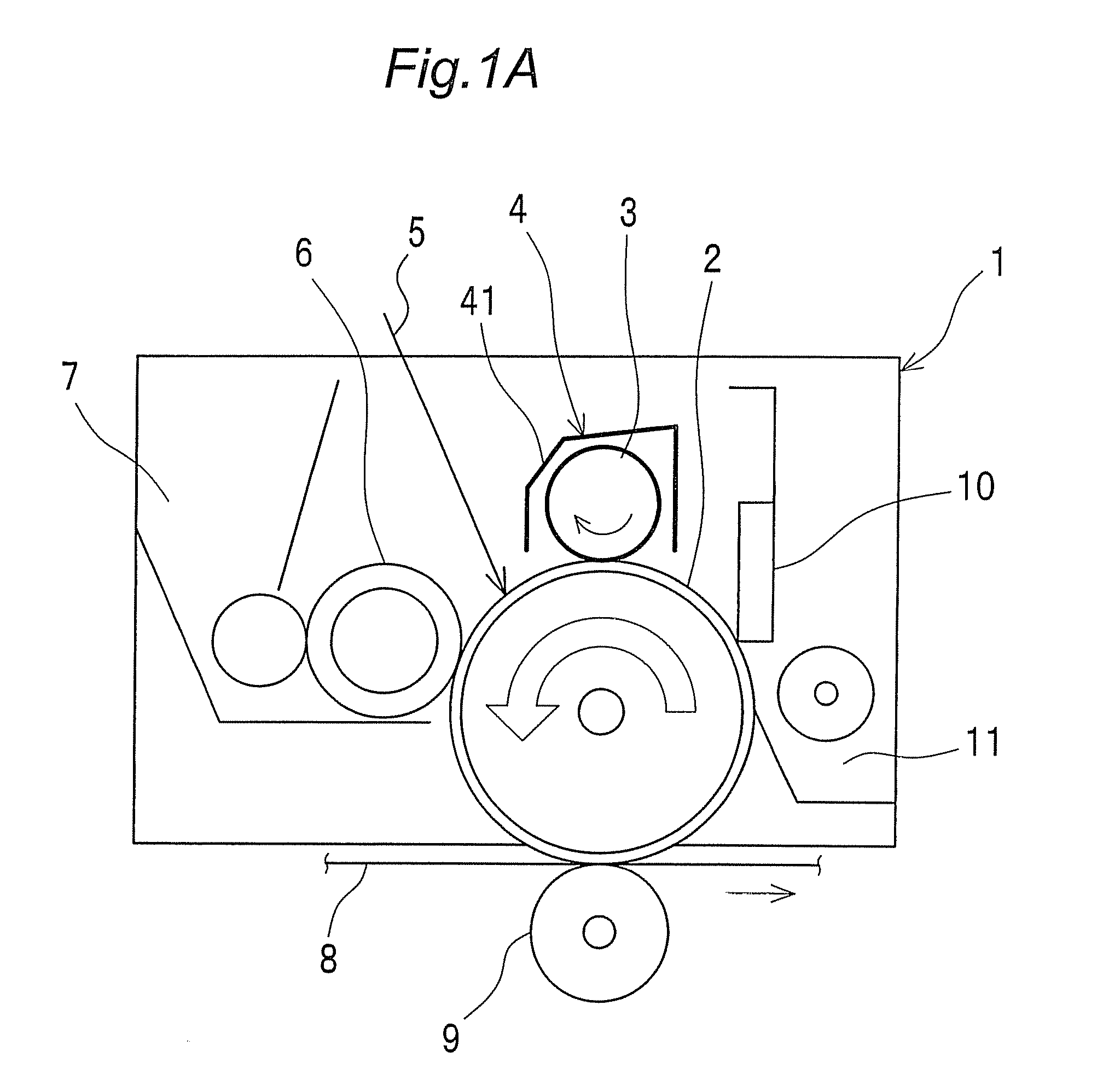
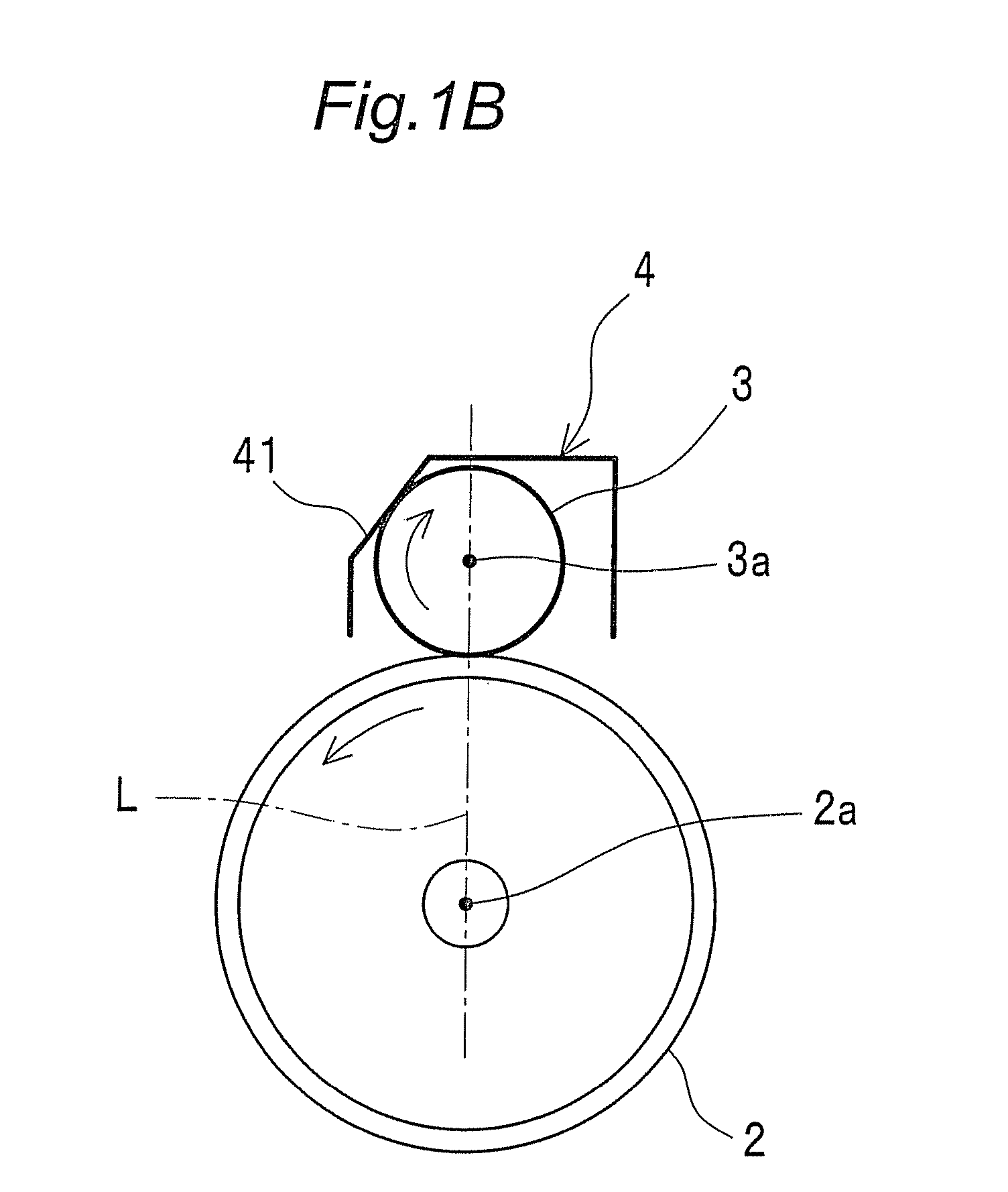
[0049]An image forming unit 1 schematically shown in FIG. 1A is provided with a photoconductor 2, a charging roller 3, a regulating member 4 surrounding the charging roller 3, a developing section 6, a toner storing section 7, a cleaner blade 10 and a toner recovery section 11. The image forming unit 1 is detachable from an image forming apparatus shown in FIG. 2. A series of operations relating to image formation are performed under the control of the apparatus.

[0050]In image formation, the photoconductor 2 is uniformly charged by the charging roller3. Based on image data, exposure is performed on the photoconductor 2 to form a latent image. Then, a toner image is formed on the photoconductor 2 in the developing section 6. An arrow 5 in the drawing shows that exposure is performed by an exposure means.

[0051]A primary transfer section 9 transfers the toner image, which is formed on the photoconductor 2, onto a paper sheet which is sent from a feed section 20 through a conveying belt...

second embodiment

[0083]An image forming unit in a second embodiment of the invention, as shown in FIGS. 6A and 6B, is different from that of the first embodiment in the structure of the pressing member. In the second embodiment, component members identical to those in the first embodiment are designated by identical reference numerals to omit explanation.

[0084]A pressing member 14 presses the charging roller 3 against at least the photoconductor 2 of both the pressing section 41E of the regulating member 4E and the photoconductor 2. That is to say, the pressing member 14 presses the charging roller 3 against both a pressing section 41E of a regulating member 4E and the photoconductor 2, as shown in FIG. 6A, or only the photoconductor 2.

[0085]The pressing member 14 is placed on both ends of the charging roller 3 in the axial direction thereof, as shown in FIG. 6B. The pressing member 14 is provided with a shaft section 14a attached to the casing 1a. The pressing section 41E contacts the charging roll...

third embodiment

[0089]An image forming unit in a third embodiment of the invention, as shown in FIG. 7, is different from that of the second embodiment in the position of the charging roller. In the third embodiment, component members identical to those in the second embodiment are designated by identical reference numerals to omit explanation.

[0090]As shown in FIG. 7A, the charging roller 3, the regulating member 4E, and the pressing member 14 are positioned below the photoconductor 2. The pressing member 14 presses the charging roller 3 against at least the photoconductor 2 of both the pressing section 41E of the regulating member 4E and the photoconductor 2.

[0091]Description is now given on the movement of the charging roller 3.

[0092]As shown in FIG. 7B, the charging roller 3 is moved by the pressing member 14 from the state shown by an imaginary line to the state by a solid line. Thereby, the charging roller 3 comes into light contact with both the photoconductor 2 and the regulating member 4E....


PUM


Abstract

An image forming unit is provided with a regulating member placed in such a way as to surround a charging roller to regulate movement thereof. The regulating member has a pressing section inclined with respect to a straight line connecting the center of the charging roller to the axis of the photoconductor, as seen from the axial direction of the photoconductor. The pressing section is inclined farther away from the photoconductor toward upstream of rotation of the photoconductor. The regulating member allows the charging roller to electrically charge the photoconductor with a simplified structure and prevents adhering substances from accumulating on the contact portion between the photoconductor and the charging roller.

Description

CROSS-REFERENCE TO RELATED APPLICATION[0001]This application is based on application No. 2008-156318 filed in Japan, the entire content of which is hereby incorporated by reference.BACKGROUND OF THE INVENTION[0002]The present invention relates to an image forming apparatus such as electrophotographic copying machines, printers and facsimiles, and to an image forming unit used for the image forming apparatus.[0003]One of conventional image forming units is provided with a rotatable photoconductor and a charging roller which has a shaft to contact with the outer face of the photoconductor (see JP 63-149669 A). This charging roller is put into pressure contact with the photoconductor by e.g. a spring which presses the shaft toward the photoconductor, so that the charging roller rotates following the rotation of the photoconductor. The charging roller applies electric charge to the photoconductor.[0004]Another conventional image forming unit applies electric charge to a photoconductor b...

Claims


Application Information

Patent Timeline
Patent Type & Authority Applications(United States)
IPC IPC(8): G03G15/02
CPCG03G15/0216
Inventor NAKAGAMI, HIDEKAZUTANAKA, YOSHINORIMORO, FUMINORISUZUKI, YASUHIROMATSUI, NAOKI
Owner KONICA MINOLTA BUSINESS TECH INC
Why Eureka
Try Eureka