Pouch-type battery

a battery and a pouch-type technology, applied in the field of pouch-type batteries, can solve the problems of increasing the manufacturing cost of batteries, difficult to form the receiving parts, and the aluminum laminate sheet may break during the compression of aluminum laminate sheets, etc., to achieve the effect of simplifying the assembly process of battery modules and manufacturing the battery modules in a more compact structur

Active Publication Date: 2009-12-17
LG ENERGY SOLUTION LTD
View PDF6 Cites 45 Cited by
  • Summary
  • Abstract
  • Description
  • Claims
  • Application Information

AI Technical Summary

Benefits of technology

[0011]Specifically, it is an object of the present invention to provide a pouch-type battery that is manufactured with a capacity equivalent to twice that of a conventional battery through a simple assembly process, and is constructed in a structure in which a battery case is prevented from breakage during the assembly process.
[0012]It is another object of the present invention to provide a pouch-type battery including a one-unit battery case constructed in a structure in which an electrode assembly is easily received in a receiving part in position, and sealing parts in contact with the atmosphere are minimized, thereby increasing the service life of the battery.Technical Solution
[0014]Consequently, the pouch-type battery according to the present invention is manufactured through a simple assembly process including a receiving part forming process, an electrode assembly mounting process, a battery case bending process, and a battery case sealing process. Also, the two receiving parts overlap with each other in position. Especially, breakage of the battery case is prevented during the receiving part forming process and the battery case bending process. Furthermore, the sealing parts through which the inside of the battery may communicate with the outside are minimized, thereby increasing the service life of the battery.
[0021]In a preferred embodiment, the battery case is constructed in a structure in which the sheets outside the receiving parts opposite to the bending line extends such that the outside sheets have a relatively large length. In this case, the battery may be manufactured by receiving the electrode assembly in one of the receiving parts, bending the battery case along the bending line, sealing all the sealing parts (inter-contact regions) excluding the extended outside sheets, injecting an electrolyte through the gap between the outside sheets, sealing the outside sheets, the cutting the sealed outside sheets into a predetermined size. Due to this structure of the battery case, it is possible to easily inject the electrolyte into the battery case, and the electrolyte is effectively prevented from overflowing due to a mistake of an operator during the injecting process.
[0022]When the battery case is constructed in the above-described structure, the inter-contact regions of the battery case may be sealed by various methods. Preferably, the sealing is accomplished by thermal welding, which increases the coupling force between the inter-contact regions of the battery case.
[0024]The medium- or large-sized battery module according to the present invention includes two electrode assemblies or an electrode assembly having a double capacity as a unit cell, and the coupling structure thereof is dense. Consequently, it is possible to simplify the assembly process of the battery module and to manufacture the battery module in a more compact structure.

Problems solved by technology

Since the thickness of the aluminum laminate sheet is small, however, the aluminum laminate sheet may break during the compression of the aluminum laminate sheet.
For this reason, it is difficult to form the receiving part such that the receiving part has a depth of 15 mm or more.
For this reason, additional guide units are needed, which increases the manufacturing costs of the battery.
As a result, the two-unit battery case is in contact with the atmosphere at all the four sides thereof, and therefore, when the two-unit battery case is used for a long period of time, a possibility of the introduction of air into the two-unit battery case greatly increases, which reduces the service life of the battery.
As a result, the mechanical strength of the laminate sheet decreases as compared to when the laminate sheet is stretched in one direction with the result that the laminate sheet may easily break during forming the receiving parts and / or bending the laminate sheet.

Method used


Image

  • Pouch-type battery
  • Pouch-type battery
  • Pouch-type battery

Examples


Embodiment Construction

[0031]Now, preferred embodiments of the present invention will be described in detail with reference to the accompanying drawings. It should be noted, however, that the scope of the present invention is not limited by the illustrated embodiments.

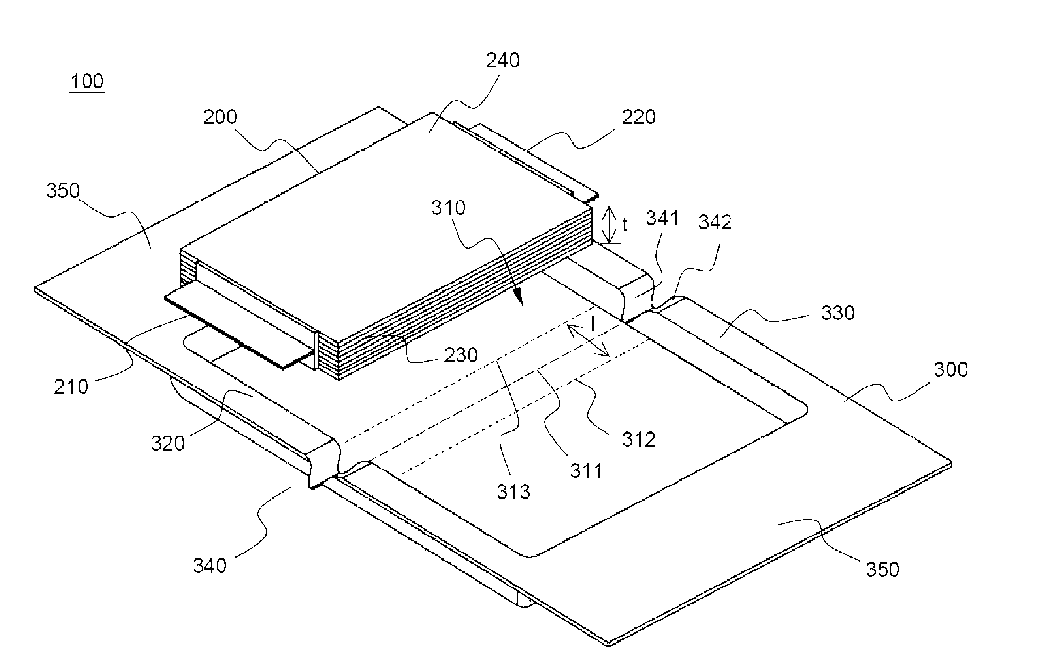
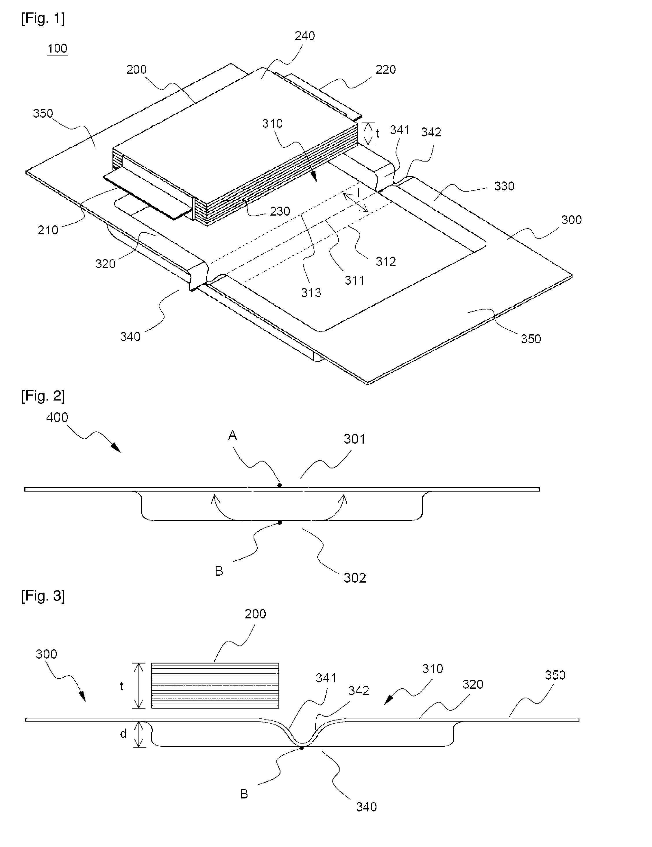
[0032]FIG. 1 is an exploded perspective view typically illustrating a pouch-type battery according to a preferred embodiment of the present invention.

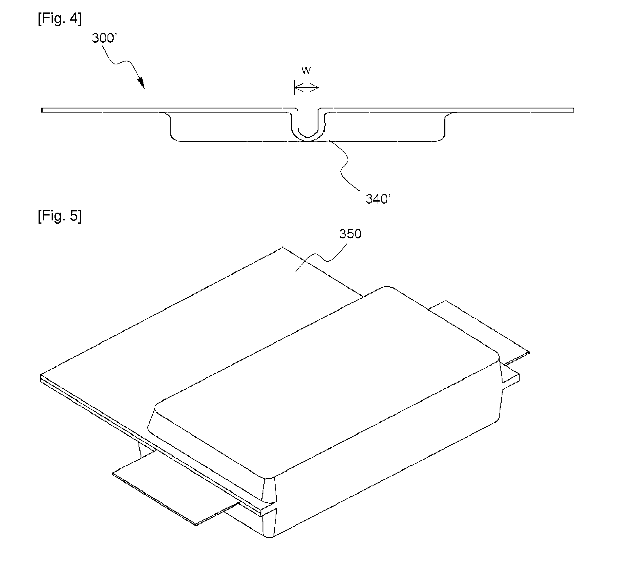
[0033]Referring to FIG. 1, the pouch-type battery 100 includes an electrode assembly 200 having a cathode 210 and an anode 220 that protrude in opposite directions and a battery case 300 having a receiving part 310 of a width greater than twice that of the electrode assembly 200 and bent depression parts 340 formed at an upper-end sealing part 320 and a lower-end sealing part 330.

[0034]The battery case 300 is bent at two bent parts 312 and 313 spaced a predetermined distance from each other about an imaginary bending line of the receiving part 310. As a result, the battery case 300 is folded su...


PUM

PropertyMeasurementUnit
depthaaaaaaaaaa
thicknessaaaaaaaaaa
thicknessaaaaaaaaaa

Abstract

Disclosed herein is a pouch-type battery including a cathode and an anode protruding from opposite sides of a battery case in opposite directions, wherein the pouch-type battery is constructed in a structure in which two receiving parts are formed at a one-unit sheet-type battery case in a symmetrical fashion such that an electrode assembly is received in the receiving parts, the battery case is bent between the two receiving parts (along a bending line) such that one of the receiving parts overlaps with the other receiving part while the electrode assembly is received in the other receiving part, the bent battery case being scaled, the two receiving parts are continuously formed while the two receiving parts are in contact with the bending line, and the battery case is provided at the edge thereof where the bending line runs with bent depression parts having a depth equivalent to that of the receiving parts. The pouch-type battery is manufactured with a capacity equivalent to twice that of a conventional battery through a simple assembly process, and is constructed in a structure in which the battery case is prevented from breakage during the assembly process.

Description

TECHNICAL FIELD[0001]The present invention relates to a pouch-type battery, and, more particularly, to a pouch-type battery including a cathode and an anode protruding from opposite sides of a battery case in opposite directions, wherein the pouch-type battery is constructed in a structure in which two receiving parts are formed in a one-unit sheet-type battery case in a symmetrical fashion such that an electrode assembly is received in the receiving parts, the battery case is bent between the two receiving parts (along a bending line) such that one of the receiving parts overlaps with the other receiving part while the electrode assembly is received in the other receiving part, the bent battery case being sealed, the two receiving parts are continuously formed while the two receiving parts are in contact with the bending line, and the battery case is provided at the edge thereof where the bending line runs with bent depression parts having a depth equivalent to that of the receivin...

Claims


Application Information

Patent Timeline
Patent Type & Authority Applications(United States)
IPC IPC(8): H01M6/12H01M2/02H01M50/105H01M50/609
CPCH01M2/0207H01M2/0287H01M2/08Y02E60/122H01M10/0436H01M10/0525H01M2/361Y02E60/10H01M50/124Y02P70/50H01M50/609H01M50/105H01M10/049H01M2220/20H01M2220/10H01M50/119H01M50/121H01M50/543H01M50/183
Inventor YOU, SEUNGJAEKIM, MIN SU
Owner LG ENERGY SOLUTION LTD
Why Eureka
Try Eureka