Bi-directional steerable sheath

Inactive Publication Date: 2009-12-17
WILSON GREATBATCH LTD
View PDF19 Cites 38 Cited by
  • Summary
  • Abstract
  • Description
  • Claims
  • Application Information

AI Technical Summary

Benefits of technology

[0007]Conventional sheath catheters do not have a step region that incorporates a combination of differing durometer materials. Instead, they are composed of lumen layers with each lumen layer composed of a monolithic polymer with a single and continuous durometer from one end to the other. The integration of a step region of

Problems solved by technology

Current sheaths however, have a limited deflection radius.
The sheath's arc of deflection is constant which therefore results in limited freedom

Method used


Image

  • Bi-directional steerable sheath
  • Bi-directional steerable sheath
  • Bi-directional steerable sheath

Examples


Embodiment Construction

[0027]As used herein, the term “durometer” relates to the hardness of a material defined as a material's resistance to permanent indentation. In the hardness measurement of polymers, elastomers and rubbers according to the present invention, durometer is measured according to ASTM D2240 type A scale.

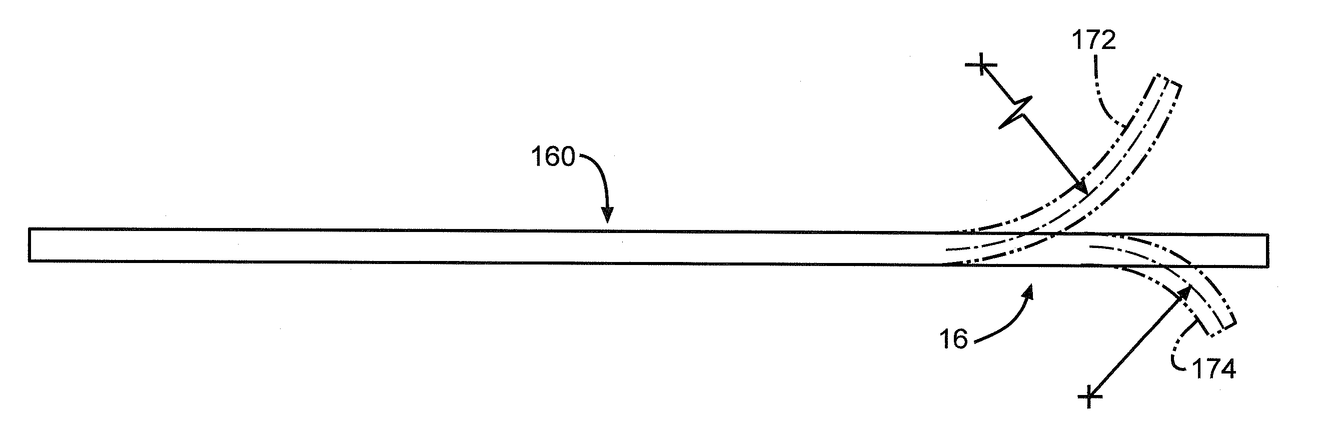
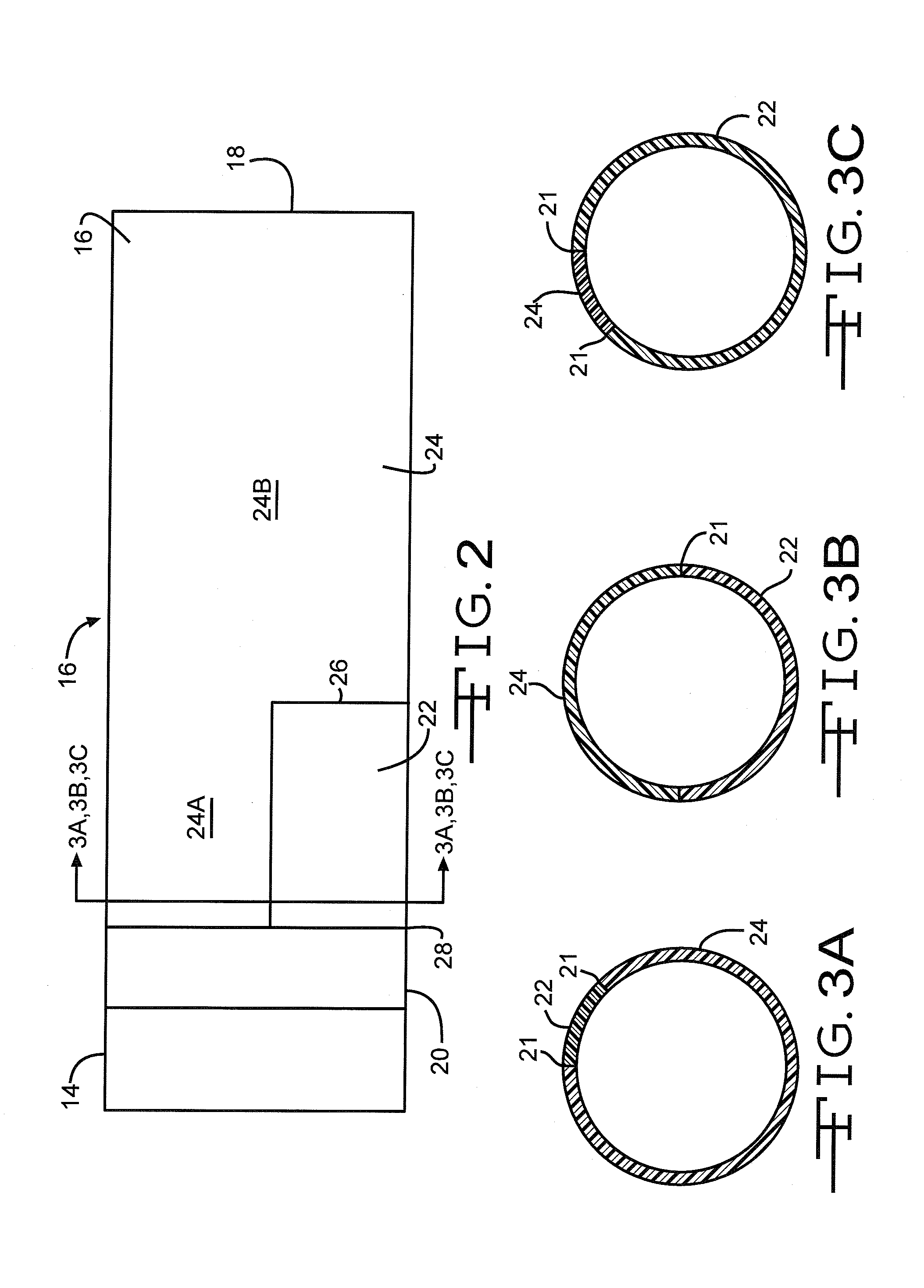
[0028]As used herein, a “step” is a transition from a first polymeric material to a second polymeric material where the first and second materials do not meet each other at an annular transition that forms a plane aligned generally perpendicular to a longitudinal axis of the sheath. An example is where the first polymeric material can range from 45° to 315° of the annular extent of the sheath member with the second polymeric material being the remainder of the annular extent along a cross-section aligned perpendicular to a longitudinal axis of the sheath. Multiple polymeric materials can be adjoined together around the catheter so as long as they together form a complete 360° annular ext...


PUM


Abstract

A deflectable sheath with increased range of curvature for human use is provided. The improvement focuses on the use of different durometer polymers that compose the lumen in the portion of deflection. The use of differing durometer polymers allow the deflectable sheath to be bent in a multitude of asymmetric curvature radii therefore providing the physician with a sheath that can traverse different regions of the body than with previous sheaths.

Description

CROSS-REFERENCE TO RELATED APPLICATION[0001]This application claims priority from U.S. provisional Application Ser. No. 61 / 061,814, filed Jun. 16, 2008.BACKGROUND OF THE INVENTIONField of the Invention[0002]The present invention generally relates to medical devices such as deflectable sheaths. More particularly, the present invention relates to a steerable sheath catheter for positioning in a desired orientation and location in the human body.SUMMARY OF THE INVENTION[0003]Many current deflectable sheaths are designed to deflect in different directions to reach locations within the human body. These sheaths are composed of overlapping monolithic polymer layers that form continuous lumen(s). A wire mesh is typically placed between the monolithic polymer layers to provide added rigidity. Pull wire(s) are typically incorporated along the length of the sheath to provide a means of deflection.[0004]Current sheaths however, have a limited deflection radius. When these sheaths are bent, the...

Claims


Application Information

Patent Timeline
IPC IPC(8): A61M25/092
CPCA61M25/0009A61M25/0054A61M25/01A61M2025/0161A61M25/0141A61M25/0147A61M25/0136
Inventor FARRELL, BRIAN K.SCHEIBE, GRANT A.PEDERSON, BRIAN
Owner WILSON GREATBATCH LTD
Why Eureka
Try Eureka