Method of designing an airfoil assembly

Inactive Publication Date: 2009-12-17
AIRBUS OPERATIONS LTD
View PDF8 Cites 8 Cited by
  • Summary
  • Abstract
  • Description
  • Claims
  • Application Information

AI Technical Summary

Benefits of technology

[0014]Associating each node with either a main airfoil element or a control surface enables the loads on the control surfaces to be modeled more accurately. Thus the higher quality of the data can result in a lighter design to be generated.
[0015]Another advantage of associating each node with either a main airfoil element or a control surface is that it enables multiple loads interfac

Problems solved by technology

A problem with the use of a simplified BAM as in Schuhmacher et al. is

Method used


Image

  • Method of designing an airfoil assembly
  • Method of designing an airfoil assembly
  • Method of designing an airfoil assembly

Examples


Embodiment Construction

)

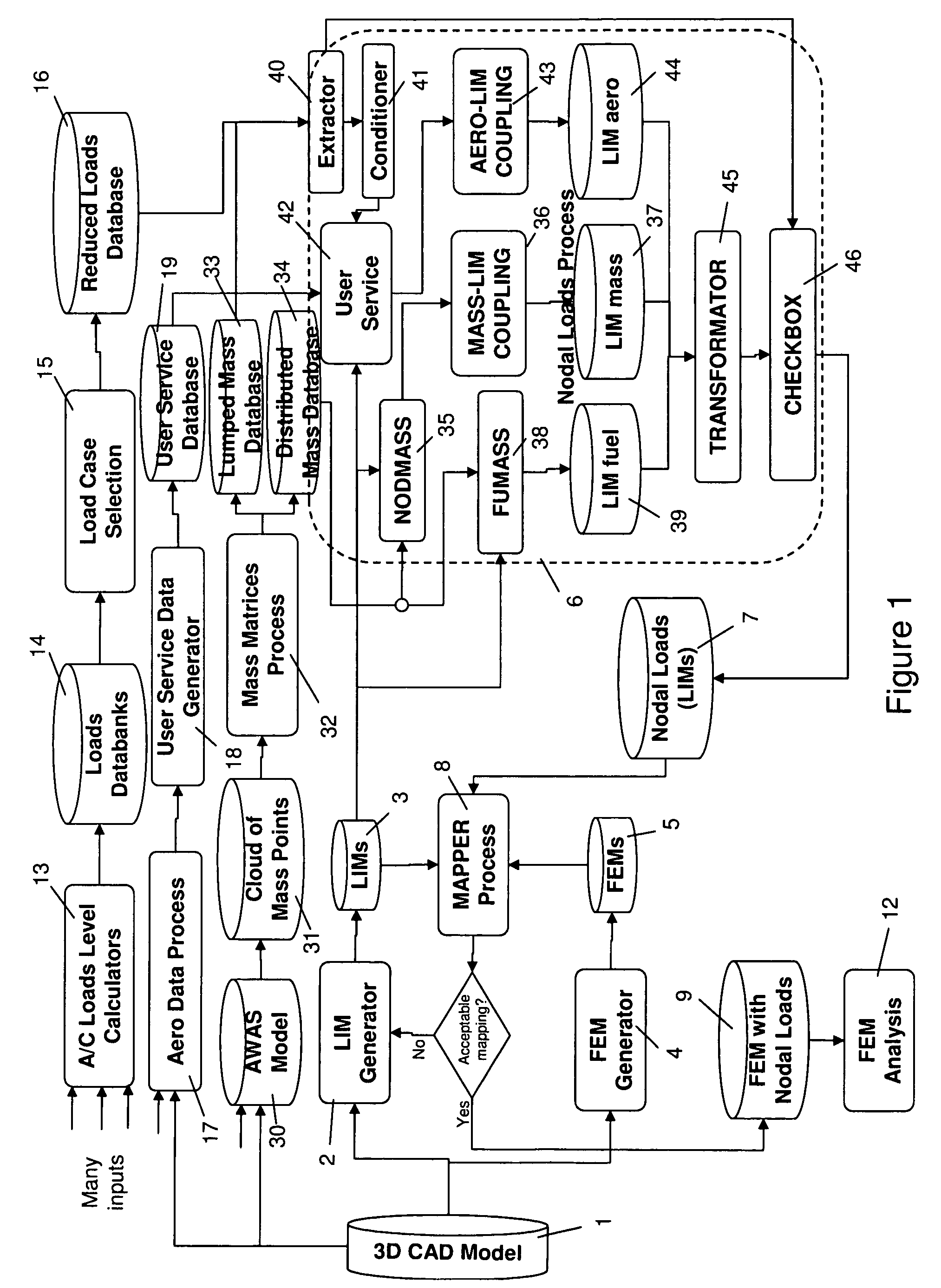
[0022]A computer-implemented method of designing an aircraft is shown in FIG. 1. A 3D computer aided design (CAD) model 1 is used by a loads interface model (LIM) generator 2 to generate a LIM of the aircraft which is stored in a database 3. The 3D CAD model 1 is also used by a finite element model (FEM) generator 4 to generate a FEM of the aircraft which is stored in a database 5.

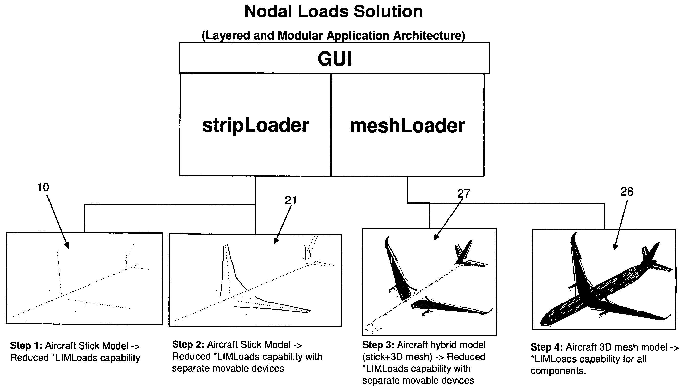
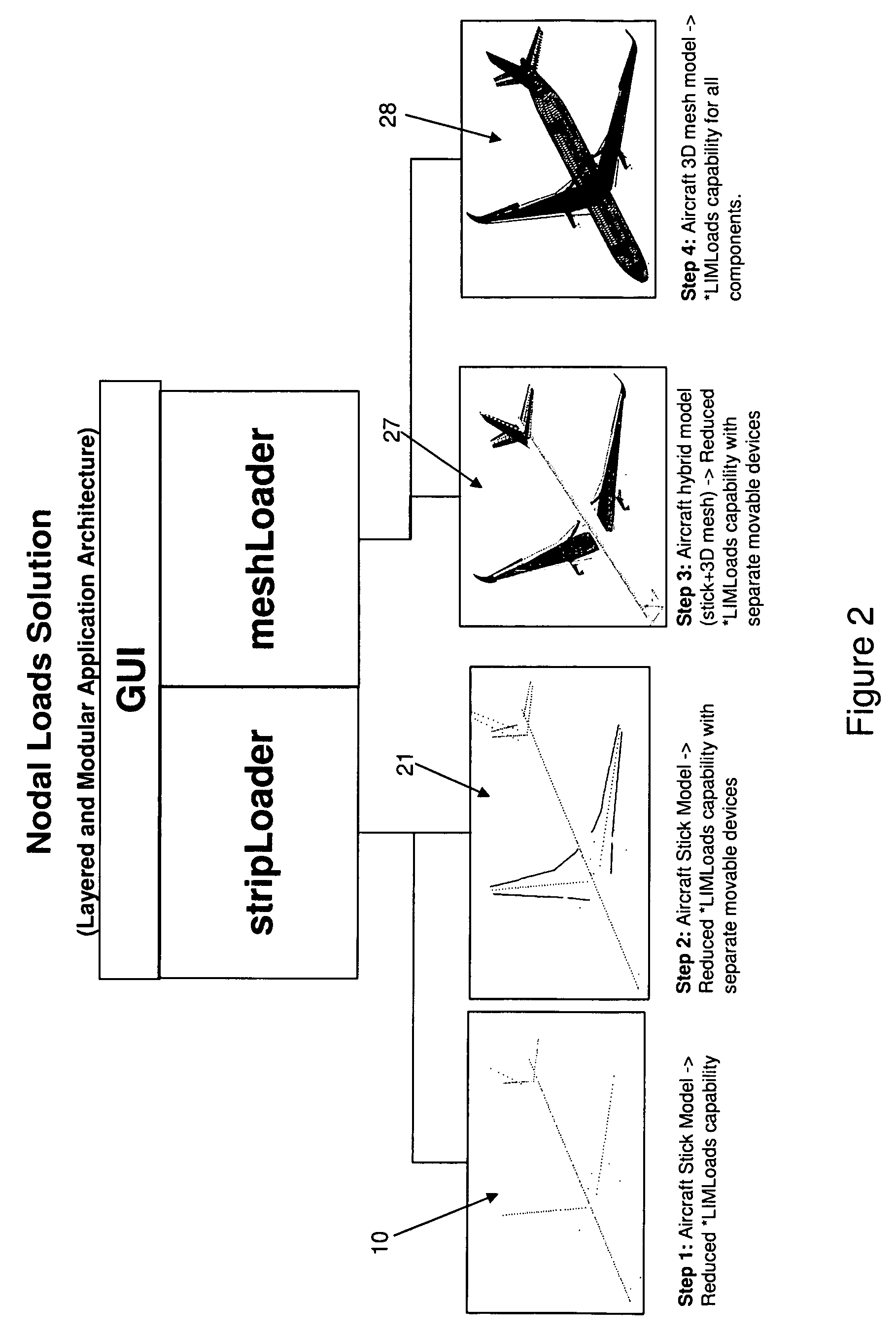
[0023]The LIM is refined in a number of steps, and a first step in the process is shown at 10 in FIG. 2. In this initial step the LIM contains data which defines the spatial coordinates of a set of nodes representing a crude stick model of the aircraft. Thus each node is either associated with the fuselage, left wing, right wing, left horizontal tail plane (HTP), right HTP or vertical tail plane. FIG. 2 also shows various more refined iterations of the LIM which will be explained further below.

[0024]The FEM 5 contains data which defines the spatial coordinates of a set of nodes, data which defines forces ...


PUM


Abstract

A method of analyzing a finite element model of an airfoil assembly. The airfoil assembly comprises a main airfoil element and a plurality of control surfaces. The method comprises: generating a loads interface model of the airfoil assembly comprising: data which defines the spatial positions of a set of nodes, and data which associates each node with either the main element or one of the control surfaces. Load data is generated which defines loads acting on the nodes of the loads interface model, and mapped onto a finite element model to produce a loaded finite element model. A stress analysis is then performed on the loaded finite element model, and the finite element model can be refined as a result of the stress analysis.

Description

FIELD OF THE INVENTION[0001]The present invention relates to a method of designing an airfoil assembly.BACKGROUND OF THE INVENTION[0002]A conventional method of designing an aircraft wing box is described in Multidisciplinary Design Optimization Of A Regional Aircraft Wing Box, G. Schuhmacher et al., AIAA. A simplified Beam Aircraft Model (BAM) is coupled with an aerodynamic panel model to analyze aero-elastic effects. It is also used by a loads group to calculate external loads resulting from flight and ground maneuvers. The loads are partitioned into aerodynamic, inertia and concentrated loads and supplied to a structures group as running loads along the elastic axes of fuselage, wing, control surfaces etc.[0003]A problem with the use of a simplified BAM as in Schuhmacher et al. is that the loads for the control surfaces and wing may not be consistent. That is, the sum of the loads acting on the wing and the control surfaces attached to the wing (flaps, ailerons etc.) may not add ...

Claims


Application Information

Patent Timeline
IPC IPC(8): G06F17/50G01L1/00G06F19/00
CPCG06F17/5095G06F17/5018G06F30/15G06F30/23
Inventor DIMITRIADIS, GEORGIOS
Owner AIRBUS OPERATIONS LTD
Why Eureka
Try Eureka