Gas sensor

Active Publication Date: 2009-12-24
DELPHI TECH IP LTD
View PDF11 Cites 36 Cited by
  • Summary
  • Abstract
  • Description
  • Claims
  • Application Information

AI Technical Summary

Benefits of technology

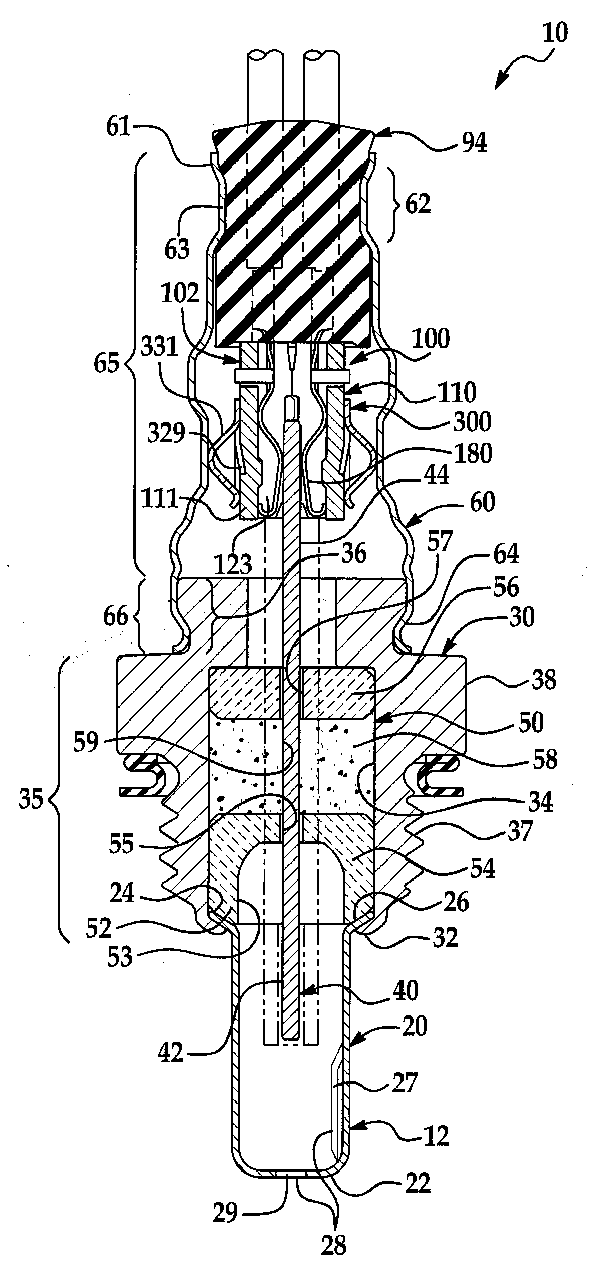
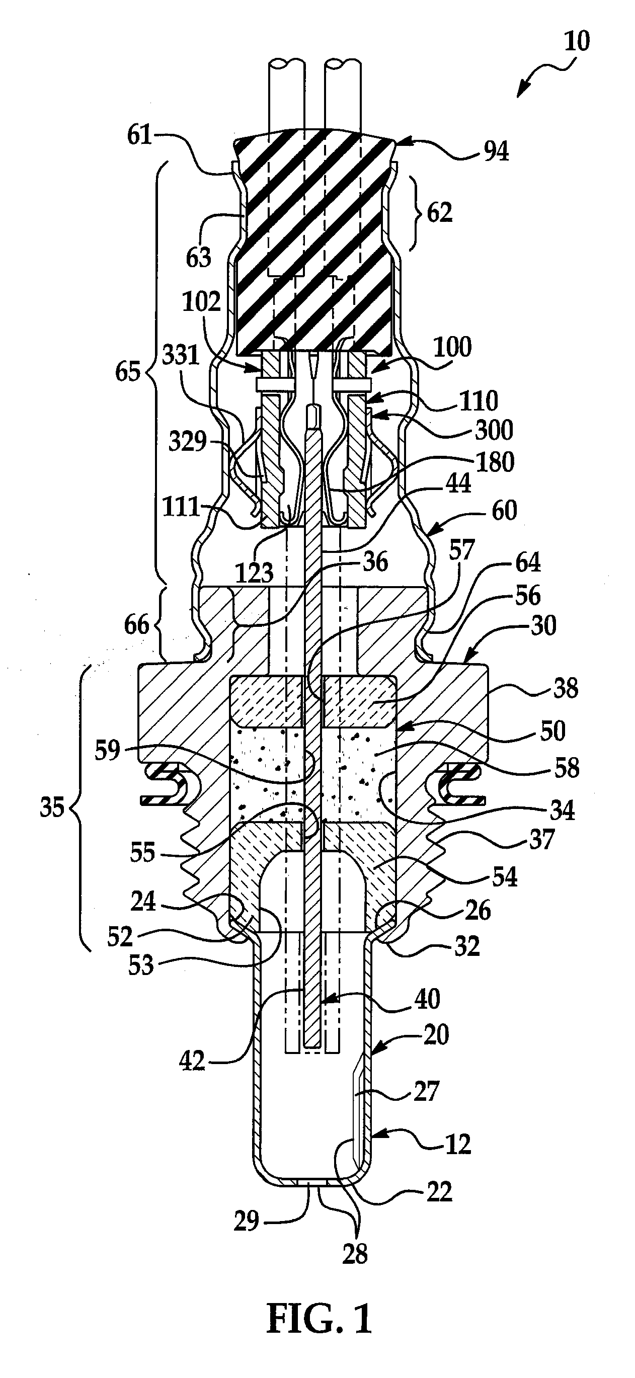
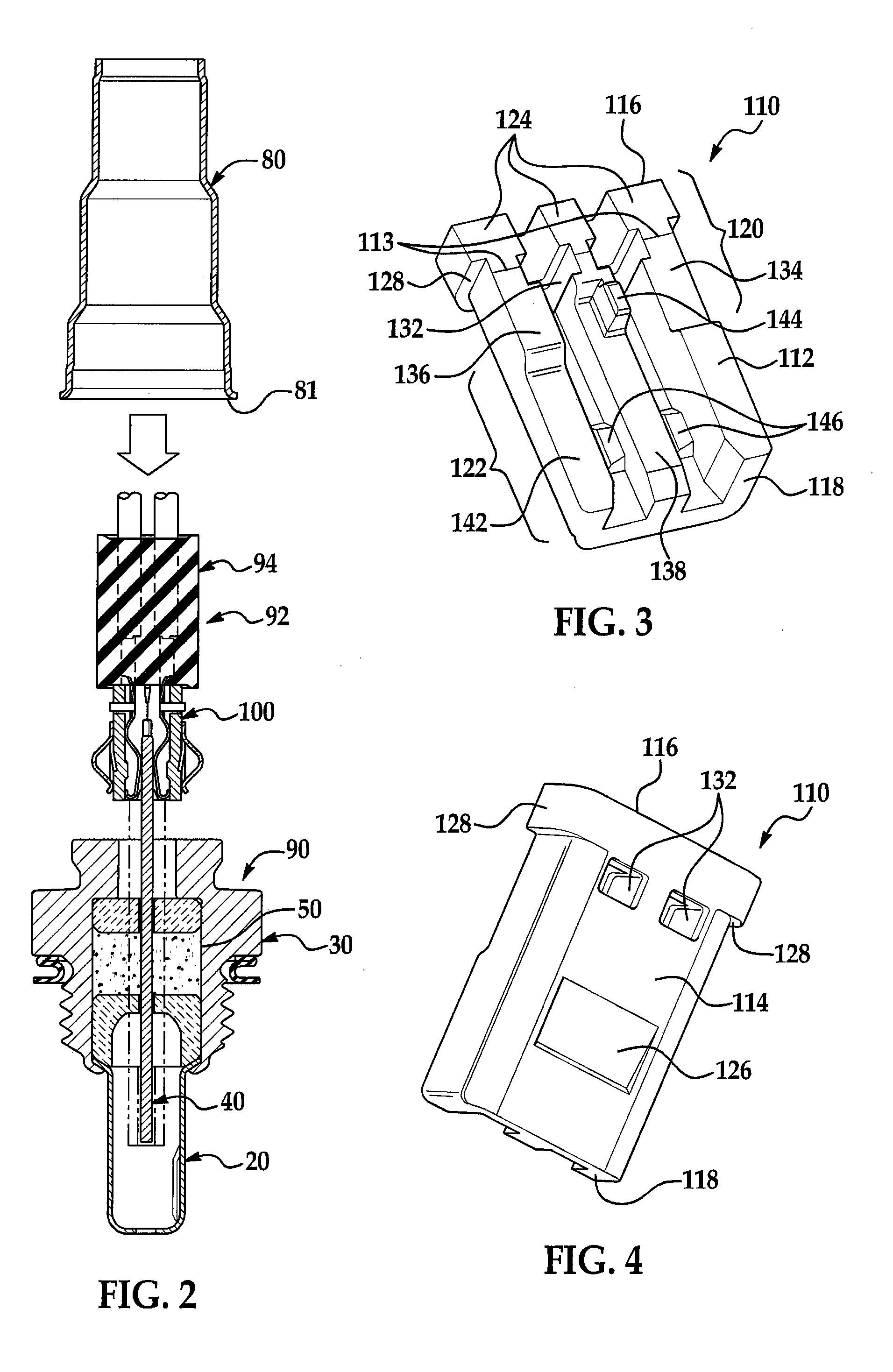
[0006]In general terms, this invention provides an improved high temperature gas sensor having an electrical connector with improved sensor insertion characteristics while maintaining sufficient contact forces after insertion, and which has a design configuration which facilitates assembly and installation of the connector. The invention also provides a method of assembling a gas sensor with an improved high temperature connector. The gas sensor of the invention includes a clamshell connector having a ceramic connector body and connector body retainer that has mixed characteristics of both edge card and clamshell connectors. It simply plugs on the end of the gas sensor like an edge card, but does so with a relatively low (e.g., less than 2 lbf) insertion force because a clamshell configuration hinges open to receive the gas sensor, and then upon hinging closed during assembly, a relatively higher (e.g., greater than 2 lbf) contact force in the fully assembled electrical connector. Sealing of the gas sensor operates to provide the contact force between the terminals of the connector and the contact pads of the sensor.

Problems solved by technology

These connectors simply plug on the end of the gas sensor; however, they frequently require relatively high (e.g., greater than 2 lbf insertion forces).
Damage to the contact pads frequently occurs; with the result that edge card connectors are generally undesirable for many gas sensor applications.
While such a design may have acceptable insertion characteristics and having A key disadvantage of such designs

Method used


Image

  • Gas sensor
  • Gas sensor
  • Gas sensor

Examples


Embodiment Construction

[0046]An exemplary embodiment of the present invention provides an improved high temperature gas sensor having a high temperature electrical connector. The electrical connector incorporates a ceramic connector body having a pair of opposing ceramic body portions which each house a plurality of conductive terminals. The body portions are in pivoting engagement and fixed in a connector body retainer which also enables their pivoting, hinged movement. The pivoting engagement permits the ceramic body portions and terminals to hinge open to receive a gas sensor with a low insertion force and a hinge closed to provide the desired contact force. The ceramic body portions may also include a taper section in a pivot portion with a taper angle that may be varied to control the pivoting, hinged movement of the electrical connector. The ceramic body portions may also include a retention pocket proximate to the connector body retainer for cooperation with outwardly extending arms of the retainer...


PUM


Abstract

A gas sensor with a high temperature electrical connector is provided. The electrical connector incorporates a ceramic connector body having a pair of opposing ceramic body portions which each house a plurality of conductive terminals. The body portions are in pivoting engagement and fixed in a connector body retainer which also enables their pivoting, hinged movement. The pivoting engagement permits the ceramic body portions and terminals to hinge open to receive a gas sensor with a low insertion force and a hinge closed to provide the desired contact force.

Description

TECHNICAL FIELD[0001]An exemplary embodiment of the present invention relates generally to high temperature gas sensors.BACKGROUND OF THE INVENTION[0002]Combustion engines that run on fossil fuels generate exhaust gases. The exhaust gases typically include oxygen as well as various undesirable pollutants. Non-limiting examples of undesirable pollutants include nitrogen oxide gases (NOx), unburned hydrocarbon gases (HC), and carbon monoxide gas (CO). Various industries, including the automotive industry, use exhaust gas sensors to both qualitatively and quantitatively sense and analyze the composition of the exhaust gases for engine control, performance improvement, emission control and other purposes, such as to sense when an exhaust gas content switches from a rich to lean or lean to rich air / fuel ratio. For example, HC emissions can be reduced using sensors that can sense the composition of oxygen gas (O2) in the exhaust gases for alteration and optimization of the air to fuel rat...

Claims


Application Information

Patent Timeline
IPC IPC(8): G01N7/00G01M15/10
CPCG01N27/4078
Inventor MCCAULEY, KATHRYN M.NELSON, CHARLES SCOTT
Owner DELPHI TECH IP LTD
Why Eureka
Try Eureka