Holding device for an ultrasonic transducer

a technology of ultrasonic transducers and holding devices, which is applied in the direction of instruments, electrical apparatus casings/cabinets/drawers, instruments, etc., can solve the problems of disadvantageous high production time and expense, large number of parts and production/assembly expenses, and relatively high cost of tools, so as to achieve high cost and production time, and save time and cost.

Inactive Publication Date: 2009-12-24
ROBERT BOSCH GMBH
View PDF26 Cites 12 Cited by
  • Summary
  • Abstract
  • Description
  • Claims
  • Application Information

AI Technical Summary

Benefits of technology

[0006]In contrast, the holding device for an ultrasonic transducer according to the present invention has the advantage of satisfying the requirement with regard to low-impedance acoustic decoupling by a low number of components, and of dispensing with an additional holding sleeve. Another advantage is that during the extrusion coating process, one component simultaneously acts as seal between the housing and the diaphragm cup in that it se

Problems solved by technology

Disadvantageous in this context are the number of parts and the production/assembly expense.
Such a form-locking bond has been tried and tested but the associated production time and expense is disadvantageously high.
Apa

Method used


Image

  • Holding device for an ultrasonic transducer
  • Holding device for an ultrasonic transducer

Examples


Embodiment Construction

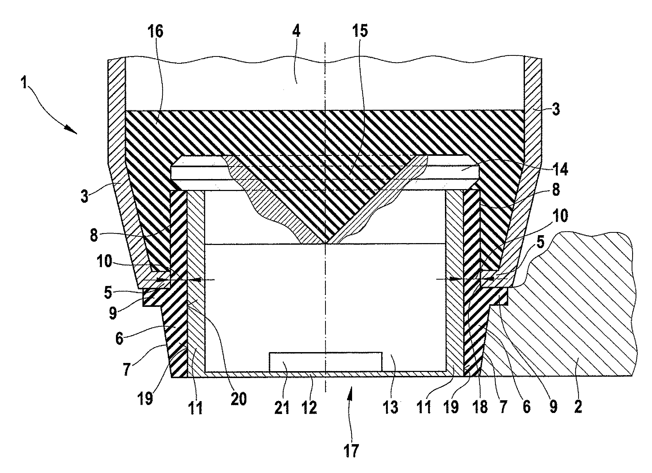
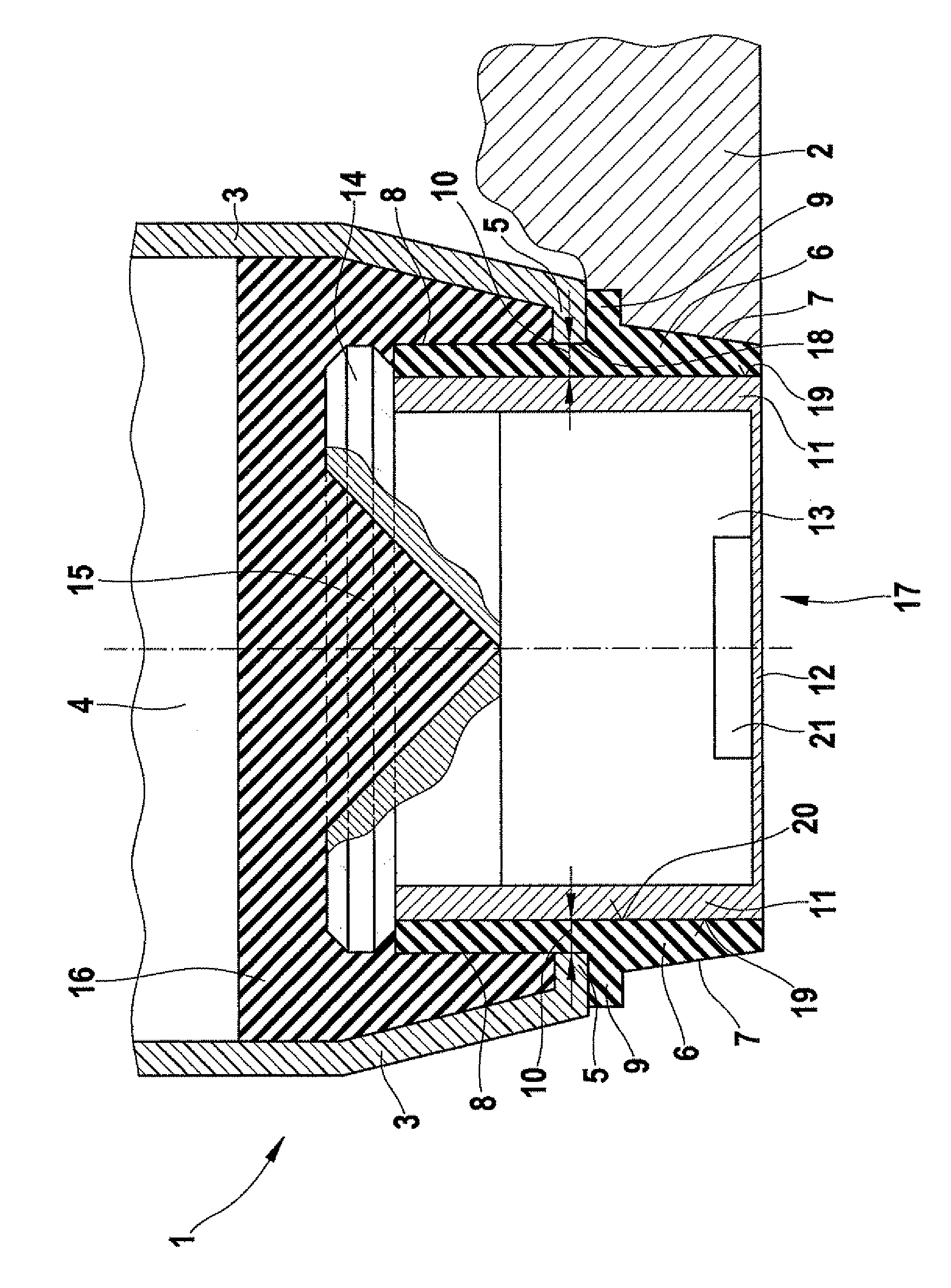
[0027]Identical or similar component parts having identical or similar functions are provided with matching reference numerals in the figures.

[0028]The single FIGURE shows an exemplary embodiment of a holding device 1 for an ultrasonic transducer 17. The components in this exemplary embodiment are dynamically balanced and shown in a sectional view.

[0029]In this exemplary embodiment, ultrasonic transducer 17 includes a diaphragm cup 11 having a diaphragm cup interior chamber 13, which is sealed on one side (the bottom side in the figures) by a diaphragm 12 on which an ultrasonic transducer element 21 is affixed inside the interior chamber. No further details of diaphragm-cup interior chamber 13 are shown for reasons of clarity. The outer side of diaphragm 12 pointing in a downward direction is used for the emission of ultrasonic waves in response to being excited by the transducer element (not shown), and for the reception of ultrasonic waves reflected off objects, such waves being t...


PUM


Abstract

A holding device for an ultrasonic transformer having a diaphragm cup, in particular for a motor vehicle, includes the following: a housing to accommodate the diaphragm cup; a decoupling component to position the diaphragm cup on the housing and on a holding section in vibration-damped manner; and a filler material to connect the diaphragm cup and the decoupling component to the housing in a vibration-damped and sealing, form-fitting manner, the decoupling component sealingly filling a gap between an edge of an opening of the housing and the diaphragm cup, as well as a corresponding method.

Description

FIELD OF THE INVENTION[0001]The present invention relates to a holding device for an ultrasonic transducer and to a corresponding method for its production.BACKGROUND INFORMATION[0002]Ultrasonic transducers of this type are used in ultrasonic sensors in motor vehicles, for instance as parking aid. These sensors are generally made up of a housing, which accommodates a diaphragm cup in whose interior a transformer element is disposed. The transformer element (e.g., a piezo element) is mounted on the bottom of the diaphragm cup, the bottom also being referred to as diaphragm. In the installed state, the outer surface of the diaphragm is exposed and excited by the transformer element for the emission of ultrasonic waves. Furthermore, it receives the ultrasonic waves reflected off an object. The ultrasonic transformer is situated inside the housing in such a way that the greatest low-acoustic impedance decoupling is obtained. The ultrasonic sensor is installed in a suitable vehicle secti...

Claims


Application Information

Patent Timeline
IPC IPC(8): H05K5/00H04R31/00
CPCG10K9/122Y10T29/49575G10K9/22
Inventor REICHE, MARTIN
Owner ROBERT BOSCH GMBH
Why Eureka
Try Eureka