Adaptive membrane structure

a membrane structure and adaptive technology, applied in the direction of humidity control, lift valve, feed/discharge of settling tanks, etc., can solve the problems of personal discomfort, difficult structure design, heavy and uncomfortable wear,

Inactive Publication Date: 2009-12-24
EI DU PONT DE NEMOURS & CO
View PDF16 Cites 32 Cited by
  • Summary
  • Abstract
  • Description
  • Claims
  • Application Information

AI Technical Summary

Problems solved by technology

It is not difficult to devise structures that are impermeable to toxic chemical vapors and liquids, but such structures are also hot, heavy and uncomfortable to wear.
When a protective fabric hinders the loss of water vapor from the body, the transpirational cooling process is hindered, which leads to personal discomfort.
When a protective suit allows little or no loss of water vapor, extreme heat stress or heat stroke can result in a short period of time.

Method used


Image

  • Adaptive membrane structure
  • Adaptive membrane structure
  • Adaptive membrane structure

Examples


example 1

[0116]Polyethylene terephthalate film, referred to herein as polyester film, sold under the trade name of Melinex® by DuPont Teijin Films, having a thickness of 196 gauge (0.00196″), was coated on one side with a thin layer of aluminum using a chemical vapor deposition process. The electrical resistance of a 2.5″ long by 2″ wide piece of aluminum-coated polyester film was measured using a two point probe apparatus. The resistance of the film was approximately 4 Ohms. The surface of the film that included the aluminum coating will be referred to as the conductive surface while the other surface that does not have the aluminum coating will be referred to as the non-conductive surface. Two circular (4″ in diameter) pieces of this polyester film were converted to a pair of membranes following the invention by punching holes through the polymer film and the conductive coating thereof. The diameter of the holes was 0.04″. Holes were punched using a VIPROS 345 turret punching machine manuf...

example 2

[0124]A pair of membranes was prepared from the same polyester film with conductive coating that was used for membranes in Example 1. The size of the holes, the hole pattern and the hole spacing in the membrane pair of this example were the same as those in the membrane pair of Example 1. The only difference between the membrane pairs of this example and the membrane pair of Example 1 was that the holes in the membrane pair of this example were created by laser drilling using a Lambda Physik (Gottingen, Germany) excimer laser Model LPX 220I operating at a wavelength of 193 nm.

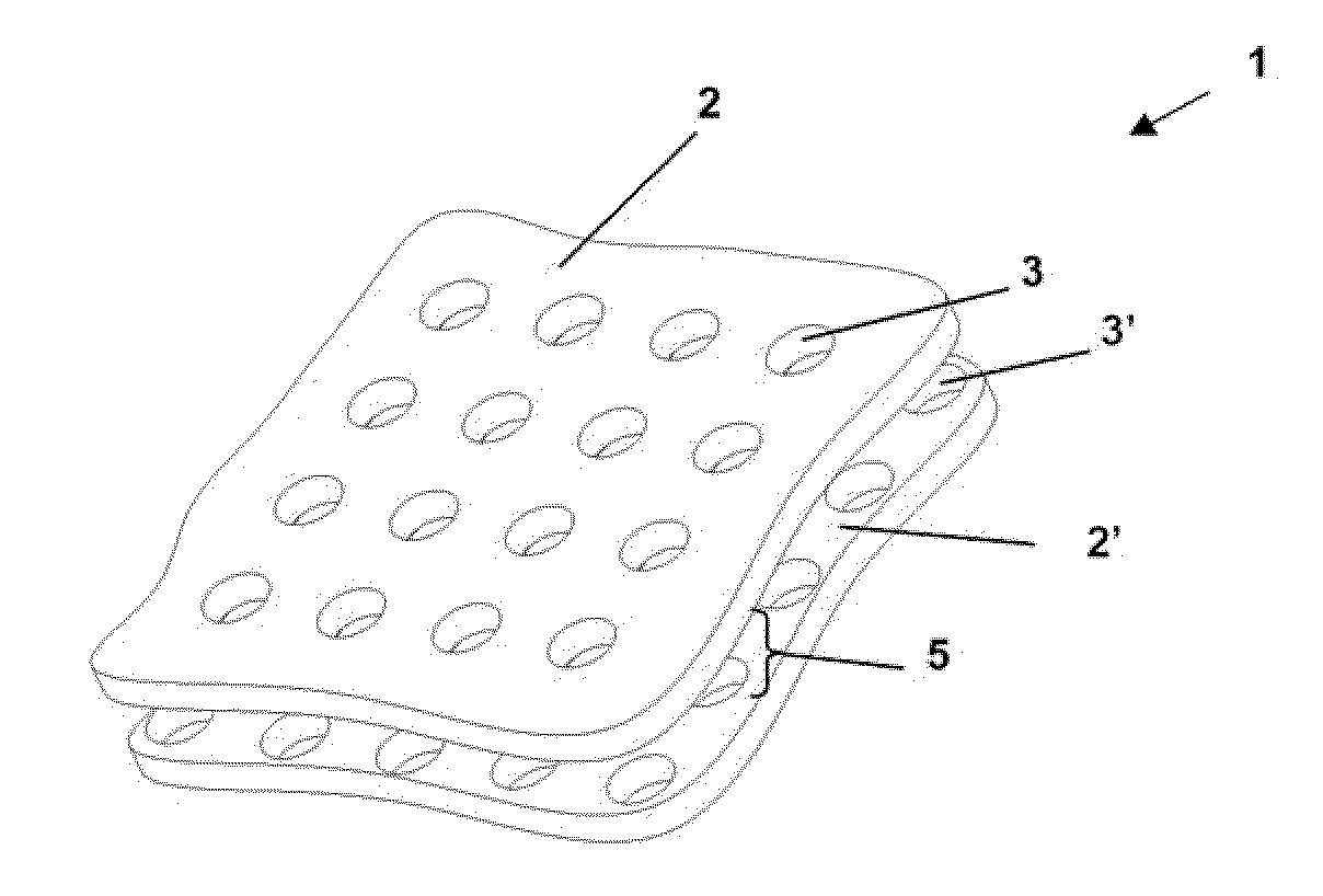
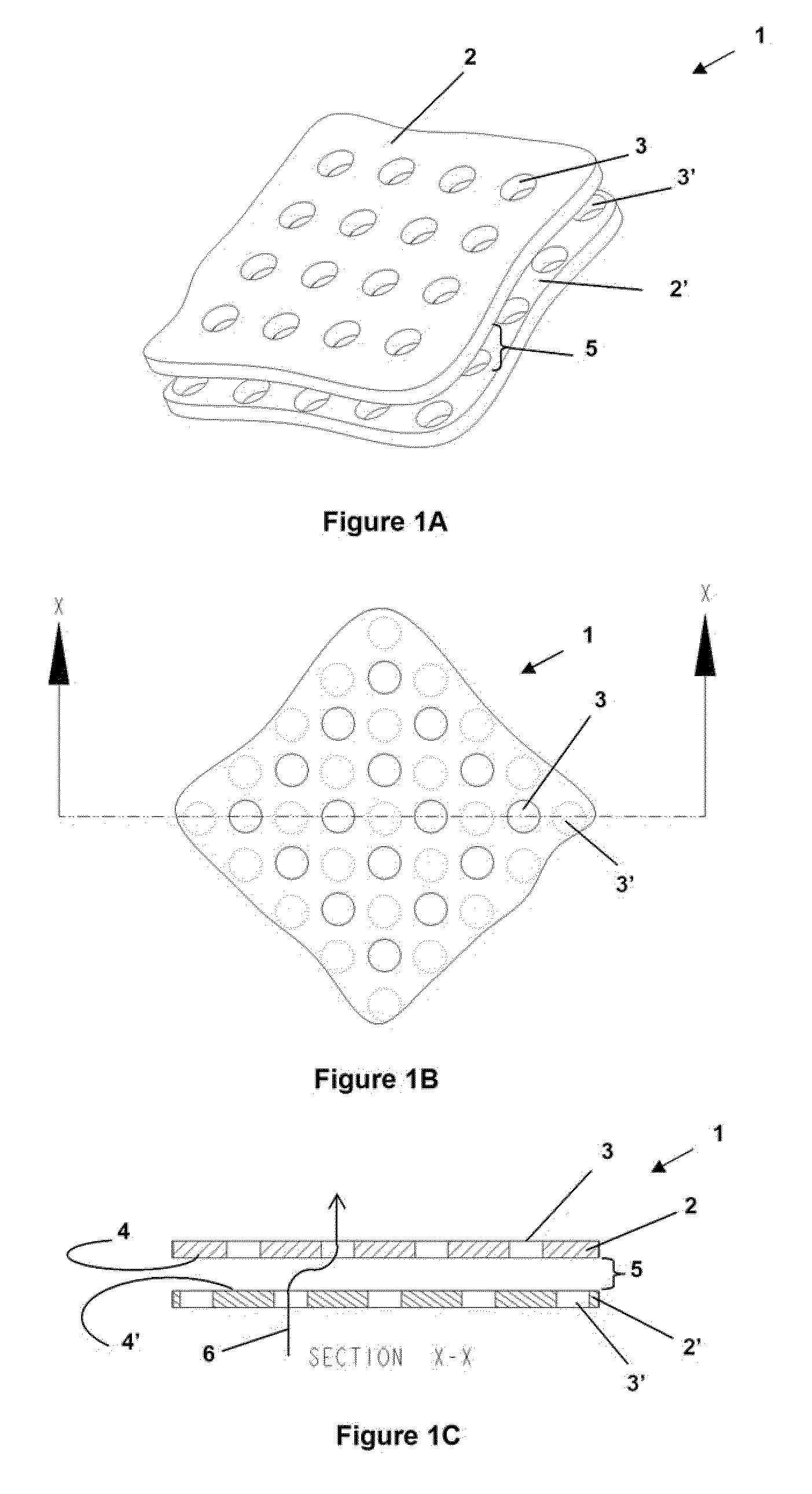
[0125]An adaptive membrane structure was created by sandwiching one polyester spacer ring, 0.004″ in thickness as described in the previous example, between the two membranes. Note that the hole pattern in the two membranes was offset from each other, and when the membranes are assembled, the holes in one membrane were thus out of registration with the holes of the other membrane. Also, when the membranes were ...

example 3

[0126]Two rectangular pieces (6″×5″) of the same polyester film with conductive coating used in Example 1 were washed for one hour in a 5 wt % aqueous solution of DuPont Oxone® monopersulfate compound, obtained from Aldrich Chemical Company, Inc. (Milwaukee, Wis.). This washing process completely removes the conductive coating from the surface of the films. The excimer laser apparatus, described in Example 2, was then used to drill holes into the uncoated polyester films. The diameter of the holes, the pattern of holes and the spacing between the holes was the same as created in the membrane pairs of Example 1 and Example 2.

[0127]The membrane pair with conductive coatings from Example 3, the uncoated membrane pair from this example and three polyester spacer rings (one between each adjacent membrane) were combined to form a membrane assembly comprising the four membranes. FIG. 17 shows the make up of the membrane assembly. When the assembly was created, care was taken to ensure that...


PUM

PropertyMeasurementUnit
areaaaaaaaaaaa
porosityaaaaaaaaaa
diameteraaaaaaaaaa

Abstract

An adaptive membrane structure is provided. The adaptive membrane structure has movable membranes that can be made to change its gas, liquid or particulate permeability in response to surrounding environmental conditions. Such adaptive membrane structures can be used to provide protective apparel that is comfortable to wear wherein the level of protection provided is based on conditions in the environment. The adaptive membrane structures can be used to provide protective enclosures.

Description

[0001]This application is a continuation-in-part of U.S. application Ser. No. 11 / 118,961, filed Apr. 29, 2005, which in turn claims the benefit of U.S. Provisional Application No. 60 / 567,357, filed Apr. 30, 2004.FIELD OF THE DISCLOSURE[0002]The present invention relates to protective articles comprising an adaptive membrane structure that can be made to change its liquid or vapor permeability in response to surrounding environmental conditions. The protective articles include protective enclosures and protective apparel wherein the level of protection provided is based on conditions in the environment.TECHNICAL BACKGROUND[0003]There is a growing need for personal protective apparel that guards against toxic chemical and biological agents. These agents may be[0004](a) accidentally released in a chemical manufacturing plant, in a scientific or medical laboratory or in a hospital;[0005](b) released intentionally during wartime by a government to attack the military forces of the opposi...

Claims


Application Information

Patent Timeline
Patent Type & Authority Applications(United States)
IPC IPC(8): B01D61/00
CPCA41D27/28Y10T428/24322A41D2400/20A41D2400/22A62B17/006B01D53/228B01D63/082B01D67/0025B01D67/0032B01D67/0034B01D67/0055B01D67/006B01D67/0062B01D67/0069B01D67/0079B01D69/02B01D69/12B01D69/147B01D71/022B01D71/24B01D71/34B01D71/48B01D71/64B01D2258/0225B01D2259/4541B01D2259/4583B01D2313/365B01D2325/02B01D2325/08B01D2325/12G05D21/02G05D22/02G05D23/19B01D2325/48A41D31/0016A41D31/102A41D31/145A41D31/305
Inventor TRENTACOSTA, JOSEPH D.KAPUR, VIVEK
Owner EI DU PONT DE NEMOURS & CO
Why Eureka
Try Eureka