Method for eliminating the need to zero and calibrate a power meter before use

a power meter and zeroing technology, applied in thermoelectric instruments, instruments, electric devices, etc., can solve the problems of inability to apply quantitatively a quantitative approach to this solution, inability to use log detectors in rf and microwave power measurement instruments, and inability to achieve excellent results in short order, so as to reduce the impact of thermal changes on measurements and large thermal mass

Active Publication Date: 2009-12-24
LADYBUG TECH
View PDF16 Cites 2 Cited by
  • Summary
  • Abstract
  • Description
  • Claims
  • Application Information

AI Technical Summary

Benefits of technology

[0050]The present invention comprises a method and apparatus that eliminates the need to calibrate or zero a power meter. Because variation in physical properties is great, it is difficult to apply a quantitative approach to this solution. Fortunately, experience indicates that minimal experimentation results in excellent results in short order.
[0066]The present invention also employs design elements and techniques present in older designs. The primary element used in almost all past designs includes use of relatively large thermal mass. Other techniques have been used in other sensors to mitigate the impact of thermal changes on measurements. This includes the characterization, measurement and compensation of ambient temperature or other the overall temperature of the sensor.

Problems solved by technology

Because variation in physical properties is great, it is difficult to apply a quantitative approach to this solution.
Fortunately, experience indicates that minimal experimentation results in excellent results in short order.
Historically, log detectors have not been used in RF and microwave power measurement instrumentation for purposes of measuring accurate power.

Method used


Image

  • Method for eliminating the need to zero and calibrate a power meter before use
  • Method for eliminating the need to zero and calibrate a power meter before use
  • Method for eliminating the need to zero and calibrate a power meter before use

Examples


Embodiment Construction

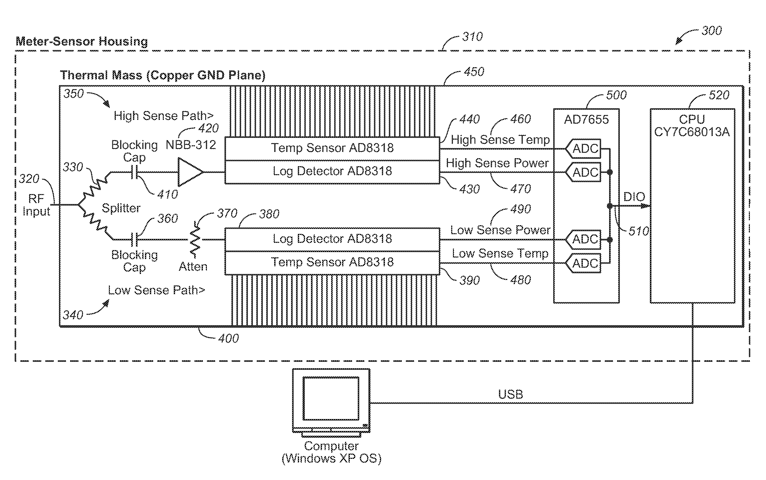
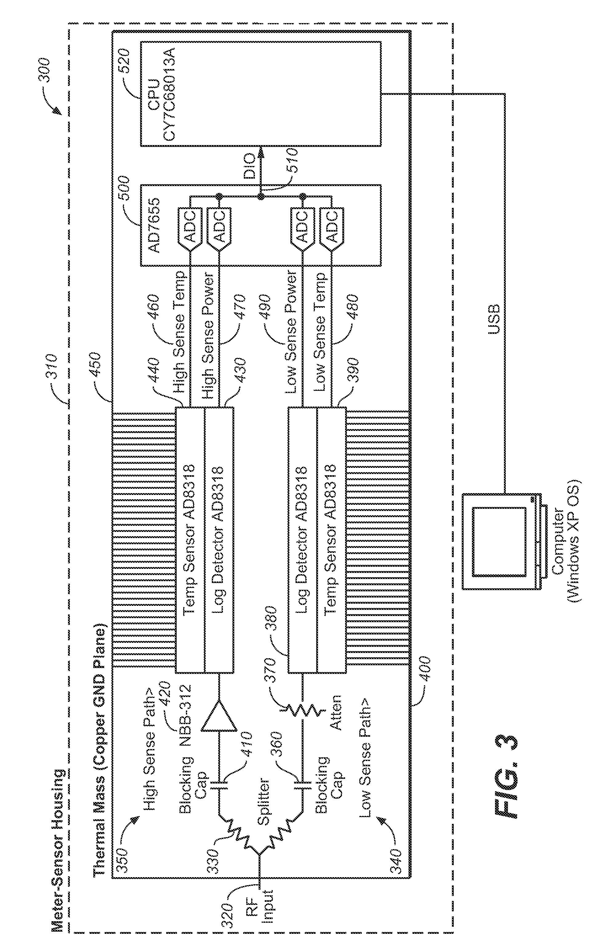
[0081]Referring now to FIG. 3, the first step in providing the improved power meter of the present invention is to isolate the incoming signal detector from the measurement port. Specifically, there is a need to ensure that any thermal transient that appears on the center conductor of the input port is not allowed to propagate to the detector. Capable engineers frequently design sensors for maximum sensitivity. Doing this requires the sensor be connected to the incoming signal with as little loss as possible. This also means the detectors are directly accessible to those same temperature changes.

[0082]The inventive design preferably includes at least one low loss attenuator or power splitter disposed between the incoming signal and the detector. As the number of thermal impediments between the incoming signal and the detector are increased, short term sensitivity is improved.

[0083]The next step is to add temperature monitoring to the detectors or to completely stabilize the detector...


PUM


Abstract

An improved power sensor having an input connector connected to an input port having a center pin and a ground side; an amplifier; first and second detectors; and a thermal stabilization system, including a thermal mass disposed between the ground side of the input connection and the detectors, a ground plane for holding the temperature of thermally sensitive components constant to within 2 degrees C., and a thermal impedance disposed between the center pin of the input port, preferably including a splitter and at least one DC capacitor, and a temperature sensor disposed on the ground plane.

Description

CROSS REFERENCES TO RELATED APPLICATIONS[0001]The present application is a divisional patent application which claims the benefit of United States Utility patent application Ser. No. 11 / 869,594 filed Oct. 9, 2007 (Oct. 9, 2007,) which application claims the benefit of U.S. Provisional Patent Application Ser. No. 60 / 828,587 filed Oct. 6, 2006 (Oct. 6, 2006.)STATEMENT REGARDING FEDERALLY SPONSORED RESEARCH OR DEVELOPMENT[0002]Not applicable.THE NAMES OR PARTIES TO A JOINT RESEARCH AGREEMENT[0003]Not applicable.INCORPORATION-BY-REFERENCE OF MATERIAL SUBMITTED ON A COMPACT Disc[0004]Not applicable.BACKGROUND OF THE INVENTION[0005]1. Field of the Invention[0006]The present invention relates generally to power meters, and more specifically to means to ensure power meter accuracy, and still more particularly to a method and apparatus that eliminates the need to calibrate or zero a power meter.[0007]2. Discussion of Related Art Including Information Disclosed Under 37 CFR 61.97, 1.98[0008]F...

Claims


Application Information

Patent Timeline
Patent Type & Authority Applications(United States)
IPC IPC(8): G01R21/02
CPCG01R35/005G01R21/02
Inventor HAWKINS, RICHARD R.SIGLER, JON R.
Owner LADYBUG TECH
Why Eureka
Try Eureka