Locked-loop quiescence apparatus, systems, and methods

a technology of quiescence apparatus and lock loop, applied in the field of apparatus, systems, and methods, can solve problems such as loss of synchronization between data bits and associated clocks

Active Publication Date: 2009-12-24
MICRON TECH INC
View PDF9 Cites 40 Cited by
  • Summary
  • Abstract
  • Description
  • Claims
  • Application Information

AI Technical Summary

Problems solved by technology

As SDRAM bandwidths increase, differential signal propagation delays across the dice may cause a loss of synchronization between data bits and associated clocks.

Method used


Image

  • Locked-loop quiescence apparatus, systems, and methods
  • Locked-loop quiescence apparatus, systems, and methods
  • Locked-loop quiescence apparatus, systems, and methods

Examples


Embodiment Construction

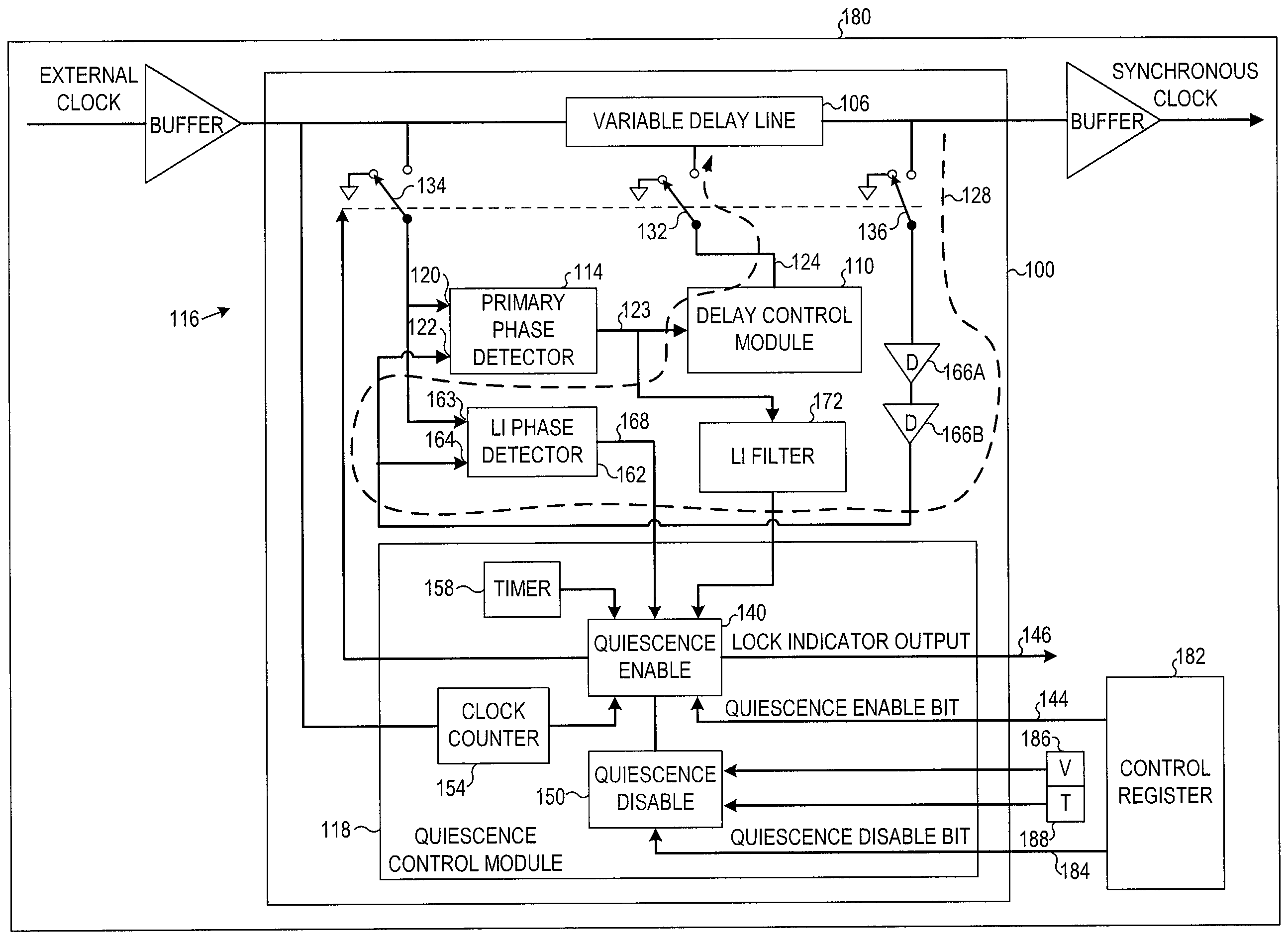
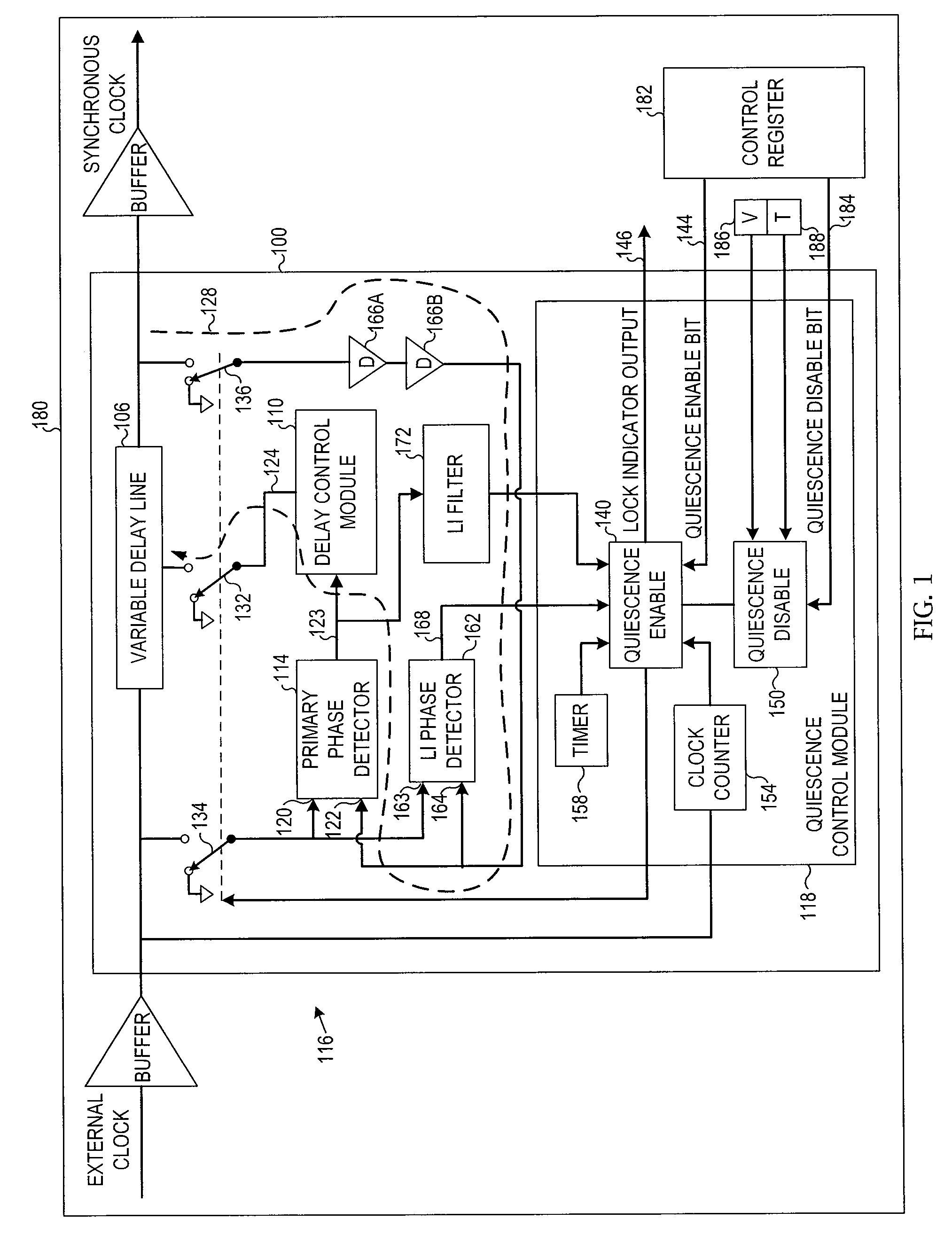
[0008]FIG. 1 is a block diagram of an apparatus 100 and a system 180 according to various embodiments of the invention. Often the incoming clock (sometimes referred to as the reference clock) associated with a DLL or a phase-locked loop (PLL) substantially meets minimum stability requirements of a circuit driven by the DLL or PLL output clock. In the latter case the DLL or PLL may be included in the circuit largely to perform a clock phase shifting function.

[0009]Embodiments herein quiesce a DLL or PLL such as to maintain a steady state in a variable delay line associated with the DLL or a variable frequency oscillator (VFO) associated with the PLL. Some embodiments may perform quiescence operations after a lock is achieved and surrounding circuitry is synchronized. Power consumption may be reduced thereby. Quiescent-mode operation may also be used in system testing to reduce timing variables caused by closed-loop operation of the DLL or PLL. In some embodiments the apparatus 100 ma...


PUM


Abstract

Apparatus, systems, and methods disclosed herein may initialize a delay-locked loop (DLL) or phase-locked loop (PLL) to achieve a locked condition and may then initiate a quiescent mode of operation. Quiescent operation may be achieved by breaking a feedback loop associated with the DLL or PLL to prevent updates to a variable delay line associated with the DLL and / or to a variable frequency oscillator associated with the PLL. An output clock phase associated with the DLL or PLL may thus be held substantially constant following a DLL initialization period. Additional embodiments are disclosed and claimed.

Description

TECHNICAL FIELD [0001]Various embodiments described herein relate to apparatus, systems, and methods associated with digital clocking and synchronization, including delay-locked loops and phase-locked loops.BACKGROUND INFORMATION [0002]Synchronous dynamic random-access memory (SDRAM) chips, including various generations of double data rate (DDR) SDRAMs, use one or more clocks to strobe data onto and off of the memory chip. Data and strobe timing signals are often synchronized to avoid ambiguities in the data bits. As SDRAM bandwidths increase, differential signal propagation delays across the dice may cause a loss of synchronization between data bits and associated clocks.[0003]Modem SDRAM may include one or more on-chip delay-locked loop (DLL) circuits to mitigate the differential delays. DLL-derived strobe circuits may be used to synchronize various SDRAM signals, including an output strobe with data appearing on the output lines. A DLL may delay a clock edge arriving from a dista...

Claims


Application Information

Patent Timeline
Patent Type & Authority Applications(United States)
IPC IPC(8): H03L7/08
CPCH03L7/0814H03L7/087G11C11/4063H03L7/095H03L7/091H03L7/0816
Inventor BECKER, ERICROTH, BRANDONSCHAFER, SCOTT
Owner MICRON TECH INC
Why Eureka
Try Eureka