Reactor core and reactor

a reactor and core technology, applied in the field of reactors, can solve the problems of large vibration generation, noise and peeling of at least a part of the adhesion surface, and the strength of the core material itself is generally lower

Active Publication Date: 2009-12-24
TOYOTA JIDOSHA KK
View PDF16 Cites 32 Cited by
  • Summary
  • Abstract
  • Description
  • Claims
  • Application Information

AI Technical Summary

Benefits of technology

[0040]FIG. 9 is a view schematically illustrating an example conventional reactor and a manufacturing method thereof.

Problems solved by technology

The powder magnetic core generally exhibits a lower Young's modulus than the laminated steel sheet, and therefore a reactor in which the powder magnetic core is used is subjected to effects of an electromagnetic attractive force in the adhesion direction between the core material and the spacer, which may result in generation of a large amount of vibration.
Generation of vibration as described above may further lead to disadvantages including generation of noise and peeling of at least a part of the adhesion surface between the core material and the gap plate.
However, particularly when a powder magnetic core is applied as the core material, the mechanical strength of the core material itself is generally lower than the core material in which a laminated steel sheet or the like is applied, and at the time of handling, such as mounting of a reactor and so on, and particularly during travelling of a vehicle in which such a reactor is mounted, the core material may suffer from deficiencies caused by vibration or the like.
Here, while it is possible to reinforce the mechanical strength of the powder magnetic core which is used as the core material to a certain degree by increasing the amount of binder, an increase in the amount of binder may degrade other desirable material characteristics such as magnetic permeability.
It is therefore very difficult to maintain these material characteristics in a desirable state while adjusting the amount of binder.
Also, because desirable material characteristics as a core material vary depending on the case in which the core material is actually used, it is very difficult and impractical to prepare core materials having various material characteristics and at the same time to increase the strength of the core material itself.

Method used


Image

  • Reactor core and reactor
  • Reactor core and reactor
  • Reactor core and reactor

Examples


embodiment 1

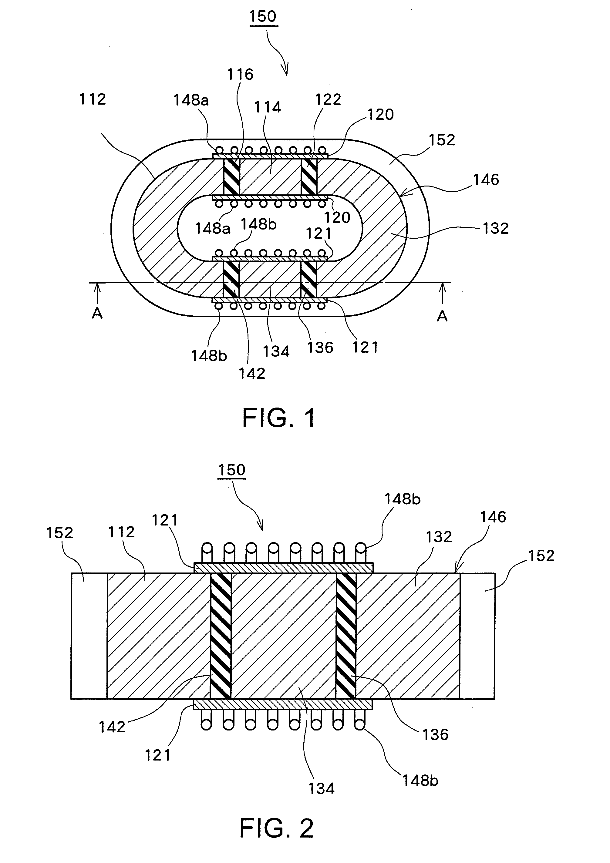
[0042]FIG. 1 is a view schematically illustrating a structure of a reactor according to an embodiment of the present invention. In FIG. 1, a reactor 150 has substantially the same structure as that of the conventional reactor 50 illustrated in FIG. 9(d) except that the reactor 150 includes a resin 152. Specifically, the reactor 150 includes an annular core 146 formed of a plurality of core materials connected with each other via spacers, and coils 148a and 148b provided on the outer peripheral surfaces of coil bobbins 120 and 121, respectively. The core 146 includes U core materials 112 and 132 having a predetermined thickness, and I core materials 114 and 134 having the same thickness as the U core materials. End surfaces of adjacent core materials are bonded together via spacers 116, 122, 136, and 142, respectively, having substantially the same thickness as the U core materials and I core materials.

[0043]The resin 152 functions as a holding material which holds the core materials...

embodiment 2

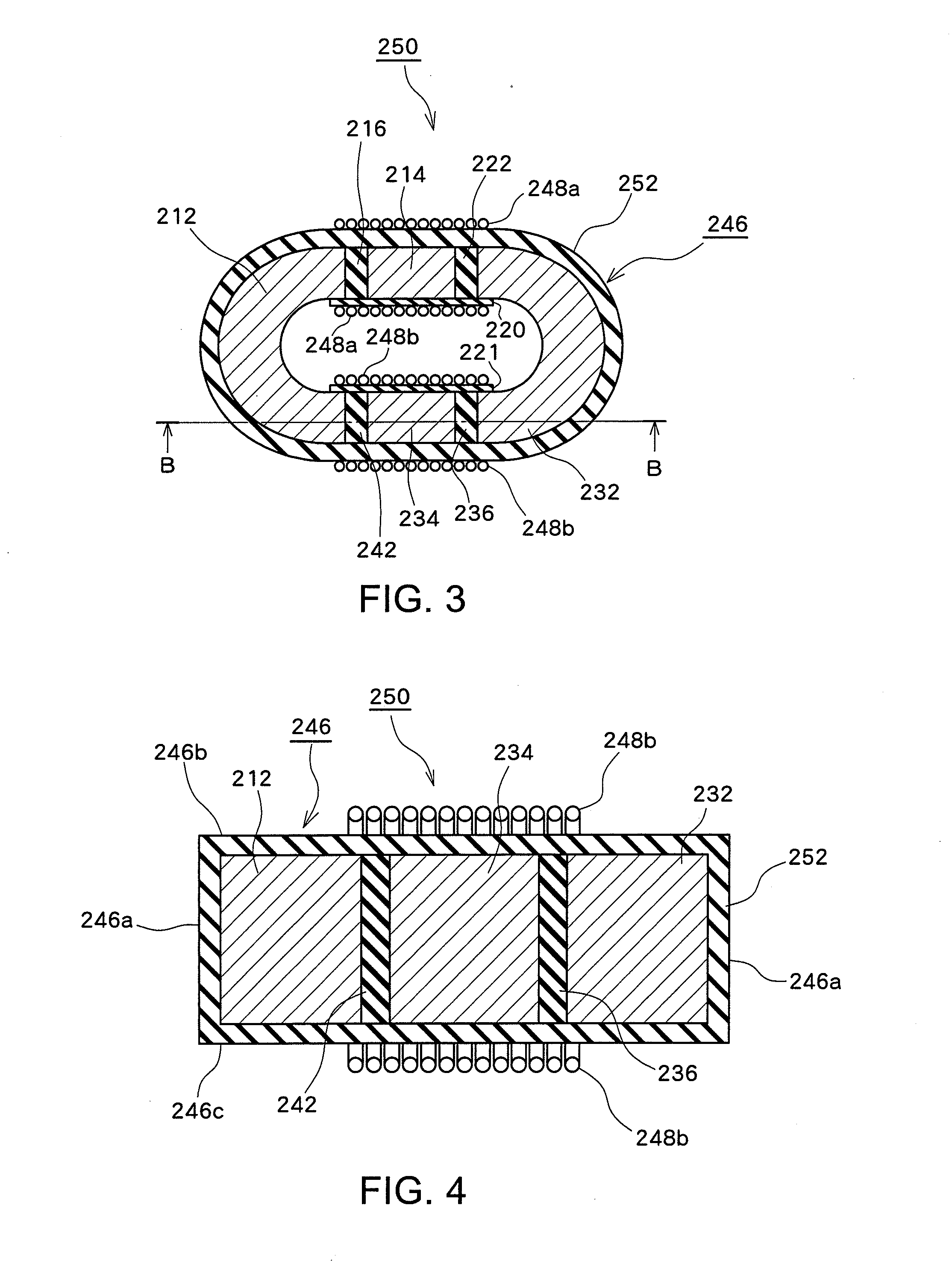
[0046]FIG. 3 is a view schematically illustrating a structure of a reactor according to another embodiment of the present invention. In FIG. 3, a reactor 250 has substantially the same structure as that of the conventional reactor 50 illustrated in FIG. 9(d) except that the reactor 250 includes a resin 252 and coil bobbins 220 and 221, in spite of the coil bobbins 20 and 21. Specifically, the reactor 250 includes an annular core 246 formed of a plurality of core materials coupled with each other via spacers, and coils 248a and 248b provided on the outer peripheral surface of core 246. Further, the core 246 includes U core materials 212 and 232 and I core materials 214 and 234. End surfaces of adjacent core materials are bonded together via spacers 216, 222, 236, and 242.

[0047]In this embodiment, the coil bobbins 220 and 221 are integrally molded with the resin 252 using the same resin material as the resin 252. The coil 248a is provided by winding around the coil bobbin 220 and a po...

embodiment 3

[0052]FIG. 5 schematically illustrates a structure of a reactor according to another embodiment of the present invention. In FIG. 5, the shape of a reactor 350 is substantially the same as that of the reactor 250 illustrated in FIG. 3, except that in the reactor 350, a resin 352 is used in place of the resin 252.

[0053]Referring to FIG. 5, the resin 352 differs from the resin 252 of FIG. 3 in that the resin 352 covers only a part of the outer periphery 346a of the core 346. Specifically, while a cross sectional shape of the reactor 350 taken along line D-D is substantially the same as the cross sectional shape of the reactor 250 in FIG. 4, a cross sectional shape of the reactor 350 taken along line C-C in FIG. 5 differs from the cross sectional shape illustrated in FIG. 4. More specifically, the resin 352 covers a part of the outer periphery 346a of the core 346 to thereby support at least a part of the core materials in the vertical direction with respect to adhesion surfaces betwee...


PUM

PropertyMeasurementUnit
particle sizeaaaaaaaaaa
temperatureaaaaaaaaaa

Abstract

In a reactor core, a gap section between a plurality of core material portions is constituted by adhering and fixing the gap section through a spacer, and a resin is arranged vertical to the adhering surface between the core material and the spacer, for sandwiching at least a part of the core material. The resin material is preferably a molded material.

Description

TECHNICAL FIELD[0001]The present invention relates to a reactor, and more particularly to a reactor mounted on a vehicle such as a hybrid vehicle.BACKGROUND ART[0002]Reactors for use in vehicles such as hybrid vehicles have a structure in which a magnetic gap having a predetermined width is formed between a plurality of core materials in order to prevent a reduction in inductance. More specifically, an integral core, which is formed by inserting a spacer such as ceramic or the like into a gap portion between each pair of core materials, and bonding the core material and the spacer which are adjacent to each other together using an adhesive, is used.[0003]FIG. 9 is a schematic view for explaining an example conventional reactor and a method of manufacture thereof. Specifically, between a core material 12 having a predetermined thickness and having an arc shape or a substantially U-shape (hereinafter referred to as a “U core material”) and a core material 14 having the same thickness ...

Claims


Application Information

Patent Timeline
Patent Type & Authority Applications(United States)
IPC IPC(8): H01F27/24
CPCH01F3/14H01F27/255H01F37/00H01F27/306H01F27/346H01F27/263
Inventor KIYONO, TAKAAKISUGIYAMA, MASAKI
Owner TOYOTA JIDOSHA KK
Why Eureka
Try Eureka