Circuit arrangement with a relay incorporating one field coil as well as switch contacts

a circuit arrangement and relay technology, applied in emergency protective circuit arrangements, relays, ac network circuit arrangements, etc., can solve problems such as low efficiency, switch contacts of relays may get soldered or glued together, and current supplied in the open condition, etc., to achieve low loss and high efficiency

Active Publication Date: 2009-12-24
SMA SOLAR TECH AG
View PDF5 Cites 10 Cited by
  • Summary
  • Abstract
  • Description
  • Claims
  • Application Information

AI Technical Summary

Benefits of technology

[0020]The trigger circuit of the invention for the relay offers the following advantages.
[0041]Instead of connecting the switch lying in the relay path on a positive side directly in series with the field coil, it is alternatively also possible that this switch of the capacitor is arranged between the capacitor and ground. As a result, safe contact opening of the relay is possible.

Problems solved by technology

Such type inverters for feeding into a mains supply are subject to particular demands.
One problem is that the switch contacts of the relays may get soldered or glued together under certain circumstances, e.g., through failures in the grid.
The disadvantage thereof is that it must be supplied with current to be in the opened condition.
Accordingly, the normally closed type involves a safety risk.
If the current supply fails, the photovoltaic plant cannot be disconnected from the grid.
Moreover, monostable relays suffer from another disadvantage.
As a result, the relay is large and expensive.
This is disadvantageous for photovoltaic inverters for feeding into a mains supply.

Method used


Image

  • Circuit arrangement with a relay incorporating one field coil as well as switch contacts
  • Circuit arrangement with a relay incorporating one field coil as well as switch contacts
  • Circuit arrangement with a relay incorporating one field coil as well as switch contacts

Examples


Embodiment Construction

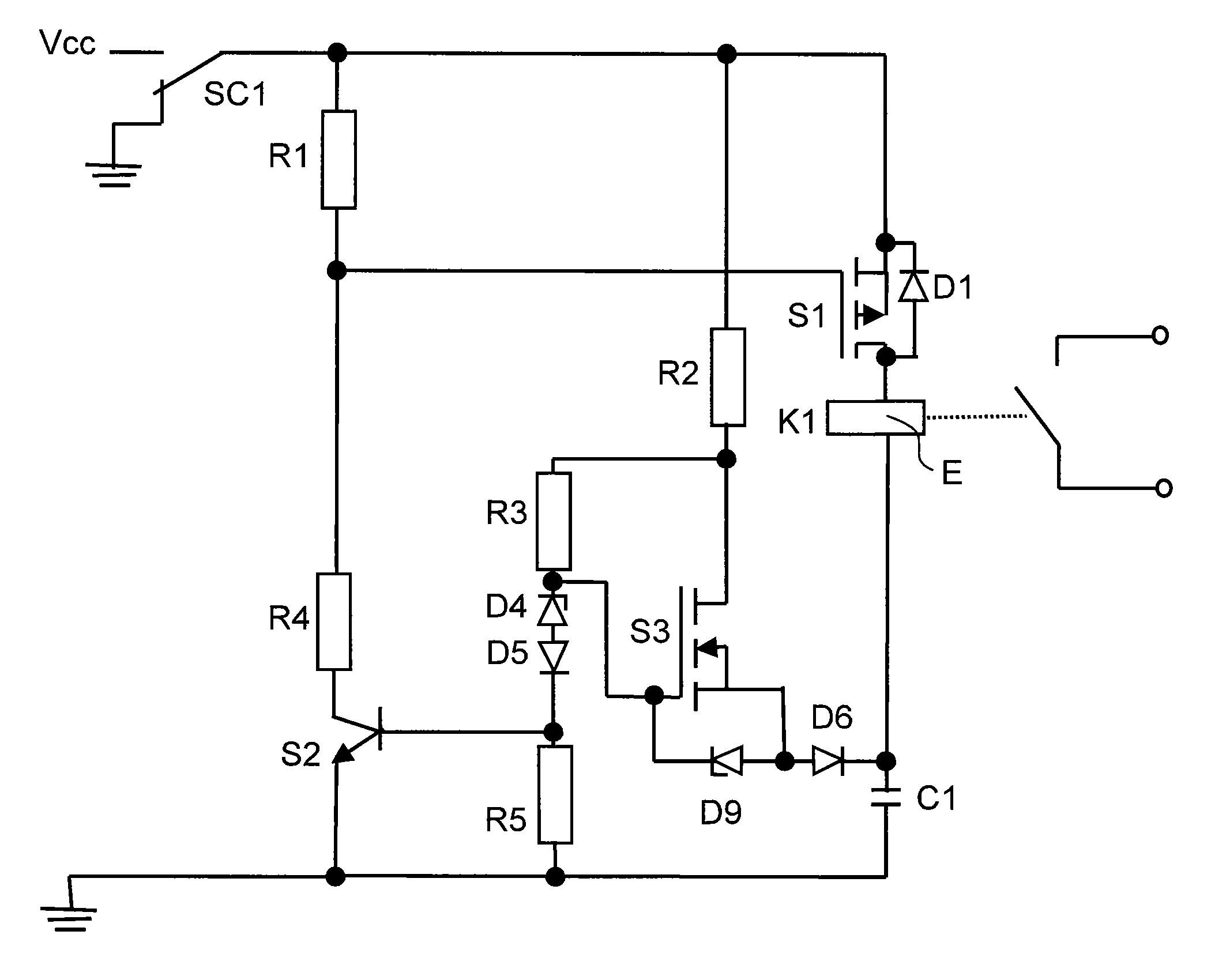
[0050]In the Figs. like components will bear the same or similar numerals. In FIG. 5, components, which are comparable to those in FIG. 4, are identified by the same reference number with the addition of an index “2”. Accordingly, the resistor R2 in FIG. 4 corresponds to the resistor R22 in FIG. 5.

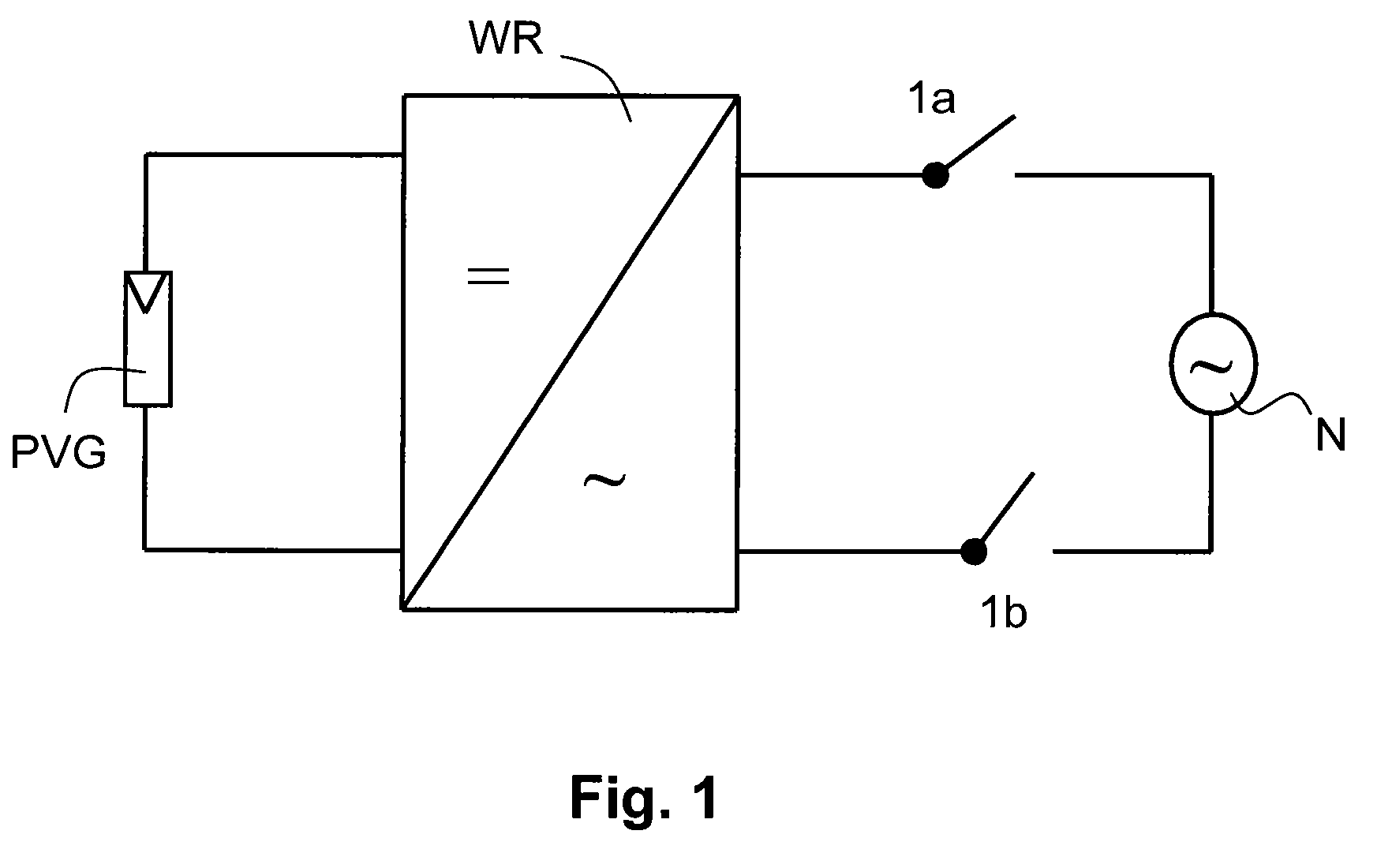
[0051]In FIG. 1, there is illustrated a photovoltaic inverter WR that is connected to a photovoltaic generator PVG and that may be connected to a mains supply N through relay or switch contacts 1a, 1b of a bistable relay.

[0052]The bistable relay is connected to a trigger circuit. The contacts 1a, 1b form a switch point of the inverter WR for feeding into the mains supply N from the photovoltaic generator PVR. The photovoltaic inverter WR converts the DC voltage of the generator PVG into an alternating current, which conforms to the grid, of e.g., 50 Hz or 60 Hz. An isolated network may also be provided instead of a mains supply.

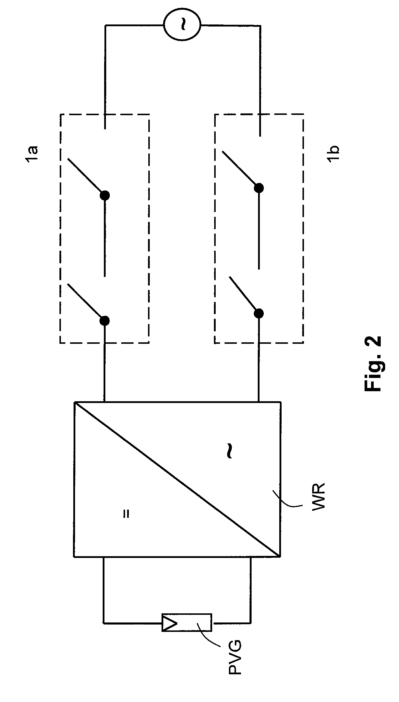
[0053]The switch point is in particular a switch point located...


PUM


Abstract

The invention is directed to a circuit array with a relay (K1; K12) incorporating a field coil (E) as well as a switch contact (1a, 1b), said switch contact (1a, 1b) being provided as a switch point between a grid, in particular a mains supply (N), and an inverter (WR) fed by a direct voltage source, in particular by a photovoltaic generator (PVG), said relay (K1; K12) being configured to be a bistable relay.

Description

BACKGROUND OF THE INVENTION[0001]The invention relates to a circuit arrangement with a relay incorporating a field coil as well as switch contacts, the switch contacts being provided as a switch point between a grid, in particular a mains supply, and an inverter fed from a direct voltage source, in particular from a photovoltaic generator.[0002]Specially devised inverters for photovoltaic plants are known, which have a semiconductor bridge circuit for feeding into a mains supply made from photovoltaic generators. Such a mains supply may be the utility grid or an isolated network. The photovoltaic inverter ensures that the direct current of the source is converted into an alternating current (AC) conforming to the mains.[0003]Such type inverters for feeding into a mains supply are subject to particular demands. They must meet safety regulations, which may vary from one country to another. What is particularly safety-relevant in almost any country is removing the photovoltaic plant, i...

Claims


Application Information

Patent Timeline
Patent Type & Authority Applications(United States)
IPC IPC(8): H01H47/00
CPCH01H47/226H02J3/383Y02E10/563H02J2300/24H02J3/381Y02E10/56H02H7/10H02J7/35
Inventor KNOPF, HANNESJEPPE, ANDREASMULLER, BURKARD
Owner SMA SOLAR TECH AG
Why Eureka
Try Eureka